Part Number: MSP430FR2433
使用eusci_a_uart_ex1_loopbackAdvanced例程,学习MSP430FR2433的时钟,在debug模式下运行一段时间暂停,看到的关于CS模块的寄存器如下:
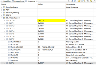
片子运行时钟SMCLK = MCLK = BRCLK = DCOCLKDIV = ~1MHz, ACLK = 32.768kHz;
即这里使用了DCO作为SMCLK的时钟源,又使用SMCLK作为波特率的时钟源,但是在初始化的时候并未对DCO进行配置;
但实际上DCOFFG显示是有错误的,这里不需要对该错误进行处理吗?
附main.c中的代码:
/* --COPYRIGHT--,BSD
* Copyright (c) 2016, Texas Instruments Incorporated
* All rights reserved.
*
* Redistribution and use in source and binary forms, with or without
* modification, are permitted provided that the following conditions
* are met:
*
* * Redistributions of source code must retain the above copyright
* notice, this list of conditions and the following disclaimer.
*
* * Redistributions in binary form must reproduce the above copyright
* notice, this list of conditions and the following disclaimer in the
* documentation and/or other materials provided with the distribution.
*
* * Neither the name of Texas Instruments Incorporated nor the names of
* its contributors may be used to endorse or promote products derived
* from this software without specific prior written permission.
*
* THIS SOFTWARE IS PROVIDED BY THE COPYRIGHT HOLDERS AND CONTRIBUTORS "AS IS"
* AND ANY EXPRESS OR IMPLIED WARRANTIES, INCLUDING, BUT NOT LIMITED TO,
* THE IMPLIED WARRANTIES OF MERCHANTABILITY AND FITNESS FOR A PARTICULAR
* PURPOSE ARE DISCLAIMED. IN NO EVENT SHALL THE COPYRIGHT OWNER OR
* CONTRIBUTORS BE LIABLE FOR ANY DIRECT, INDIRECT, INCIDENTAL, SPECIAL,
* EXEMPLARY, OR CONSEQUENTIAL DAMAGES (INCLUDING, BUT NOT LIMITED TO,
* PROCUREMENT OF SUBSTITUTE GOODS OR SERVICES; LOSS OF USE, DATA, OR PROFITS;
* OR BUSINESS INTERRUPTION) HOWEVER CAUSED AND ON ANY THEORY OF LIABILITY,
* WHETHER IN CONTRACT, STRICT LIABILITY, OR TORT (INCLUDING NEGLIGENCE OR
* OTHERWISE) ARISING IN ANY WAY OUT OF THE USE OF THIS SOFTWARE,
* EVEN IF ADVISED OF THE POSSIBILITY OF SUCH DAMAGE.
* --/COPYRIGHT--*/
//******************************************************************************
//! EUSCI_A0 External Loopback test using EUSCI_A_UART_init API
//!
//! Description: This demo connects TX to RX of the MSP430 UART
//! The example code shows proper initialization of registers
//! and interrupts to receive and transmit data.
//!
//! SMCLK = MCLK = BRCLK = DCOCLKDIV = ~1MHz, ACLK = 32.768kHz
//!
//!
//! Tested on MSP430FR4133
//! -----------------
//! RST -| P1.0/UCA0TXD|----|
//! | | |
//! | | |
//! | P1.1/UCA0RXD|----|
//! | |
//!
//! This example uses the following peripherals and I/O signals. You must
//! review these and change as needed for your own board:
//! - UART peripheral
//! - GPIO Port peripheral (for UART pins)
//! - UCA0TXD
//! - UCA0RXD
//!
//! This example uses the following interrupt handlers. To use this example
//! in your own application you must add these interrupt handlers to your
//! vector table.
//! - USCI_A0_VECTOR.
//******************************************************************************
#include "driverlib.h"
uint16_t i;
uint8_t RXData = 0, TXData = 0;
uint8_t check = 0;
uint32_t clockValue;
void main(void)
{
// stop watchdog
WDT_A_hold(WDT_A_BASE);
// XT1 Setup
//Set P4.1 and P4.2 as Function Input.
/*
* Select Port 4
* Set Pin 1, 2 to input Module Function, XT1.
*/
GPIO_setAsPeripheralModuleFunctionInputPin(
GPIO_PORT_P2,
GPIO_PIN0 + GPIO_PIN1,
GPIO_PRIMARY_MODULE_FUNCTION
);
//Set external clock frequency to 32.768 KHz
CS_setExternalClockSource(32768);
//Set ACLK=XT1
CS_initClockSignal(CS_ACLK,CS_XT1CLK_SELECT,CS_CLOCK_DIVIDER_1);
//Start XT1 with no time out
CS_turnOnXT1(CS_XT1_DRIVE_0);
//Set SMCLK = DCO with frequency divider of 1
CS_initClockSignal(CS_SMCLK,CS_DCOCLKDIV_SELECT,CS_CLOCK_DIVIDER_1);
//Set MCLK = DCO with frequency divider of 1
CS_initClockSignal(CS_MCLK,CS_DCOCLKDIV_SELECT,CS_CLOCK_DIVIDER_1);
// Configure UART pins
//Set P1.0 and P1.1 as Secondary Module Function Input.
/*
* Select Port 1
* Set Pin 0, 1 to input with function, (UCA0TXD/UCA0SIMO, UCA0RXD/UCA0SOMI).
*/
GPIO_setAsPeripheralModuleFunctionInputPin(
GPIO_PORT_P1,
GPIO_PIN4 + GPIO_PIN5,
GPIO_PRIMARY_MODULE_FUNCTION
);
/*
* Disable the GPIO power-on default high-impedance mode to activate
* previously configured port settings
*/
PMM_unlockLPM5();
//Configure UART
//SMCLK = 1MHz, Baudrate = 115200
//UCBRx = 8, UCBRFx = 0, UCBRSx = 0xD6, UCOS16 = 0
EUSCI_A_UART_initParam param = {0};
param.selectClockSource = EUSCI_A_UART_CLOCKSOURCE_SMCLK;
param.clockPrescalar = 8;
param.firstModReg = 0;
param.secondModReg = 0xD6;
param.parity = EUSCI_A_UART_NO_PARITY;
param.msborLsbFirst = EUSCI_A_UART_LSB_FIRST;
param.numberofStopBits = EUSCI_A_UART_ONE_STOP_BIT;
param.uartMode = EUSCI_A_UART_MODE;
param.overSampling = EUSCI_A_UART_LOW_FREQUENCY_BAUDRATE_GENERATION;
if(STATUS_FAIL == EUSCI_A_UART_init(EUSCI_A0_BASE, ¶m))
{
return;
}
EUSCI_A_UART_enable(EUSCI_A0_BASE);
EUSCI_A_UART_clearInterrupt(EUSCI_A0_BASE,
EUSCI_A_UART_RECEIVE_INTERRUPT);
// Enable USCI_A0 RX interrupt
EUSCI_A_UART_enableInterrupt(EUSCI_A0_BASE,
EUSCI_A_UART_RECEIVE_INTERRUPT); // Enable interrupt
//Verify if the Clock settings are as expected
clockValue = CS_getMCLK();
clockValue = CS_getACLK();
clockValue = CS_getSMCLK();
__enable_interrupt();
while(1)
{
TXData = TXData + 1; // Increment TX data
// Load data onto buffer
EUSCI_A_UART_transmitData(EUSCI_A0_BASE,
TXData);
while(check != 1)
{
;
}
check = 0;
}
}
//******************************************************************************
//
//This is the USCI_A0 interrupt vector service routine.
//
//******************************************************************************
#if defined(__TI_COMPILER_VERSION__) || defined(__IAR_SYSTEMS_ICC__)
#pragma vector=USCI_A0_VECTOR
__interrupt
#elif defined(__GNUC__)
__attribute__((interrupt(USCI_A0_VECTOR)))
#endif
void EUSCI_A0_ISR(void)
{
switch(__even_in_range(UCA0IV,USCI_UART_UCTXCPTIFG))
{
case USCI_NONE: break;
case USCI_UART_UCRXIFG:
RXData = EUSCI_A_UART_receiveData(EUSCI_A0_BASE);
if(!(RXData == TXData)) // Check value
{
while(1)
{
;
}
}
check = 1;
break;
case USCI_UART_UCTXIFG: break;
case USCI_UART_UCSTTIFG: break;
case USCI_UART_UCTXCPTIFG: break;
}
}