这是msp430g2xx3_uscib0_i2c_09例程,i2c从机接收数据的程序,请高手指点一下,为什么读取UCB0RXBUF是在发送中断中?接收机是在什么时候进入发送中断的?
#include <msp430.h>
unsigned char *PRxData; // Pointer to RX data
unsigned char RXByteCtr;
volatile unsigned char RxBuffer[128]; // Allocate 128 byte of RAM
int main(void)
{
BCSCTL2|=DIVS_3;
WDTCTL = WDTPW + WDTHOLD; // Stop WDT
P1SEL |= BIT6 + BIT7; // Assign I2C pins to USCI_B0
P1SEL2|= BIT6 + BIT7; // Assign I2C pins to USCI_B0
UCB0CTL1 |= UCSWRST; // Enable SW reset
UCB0CTL0 = UCMODE_3 + UCSYNC; // I2C Slave, synchronous mode
UCB0I2COA = 0x48; // Own Address is 048h
UCB0CTL1 &= ~UCSWRST; // Clear SW reset, resume operation
UCB0I2CIE |= UCSTPIE + UCSTTIE; // Enable STT and STP interrupt
IE2 |= UCB0RXIE; // Enable RX interrupt
while (1)
{
PRxData = (unsigned char *)RxBuffer; // Start of RX buffer
RXByteCtr = 0; // Clear RX byte count
__bis_SR_register(CPUOFF + GIE); // Enter LPM0 w/ interrupts
// Remain in LPM0 until master
// finishes TX
__no_operation(); // Set breakpoint >>here<< and read
} // read out the RxData buffer
}
//------------------------------------------------------------------------------
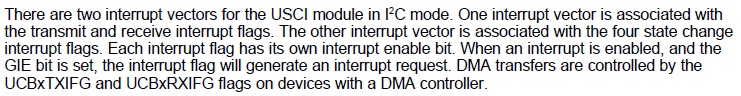
// The USCI_B0 data ISR is used to move received data from the I2C master
// to the MSP430 memory.
//------------------------------------------------------------------------------
#pragma vector = USCIAB0TX_VECTOR
__interrupt void USCIAB0TX_ISR(void)
{
*PRxData++ = UCB0RXBUF; // Move RX data to address PRxData
RXByteCtr++; // Increment RX byte count
}
//------------------------------------------------------------------------------
// The USCI_B0 state ISR is used to wake up the CPU from LPM0 in order to
// process the received data in the main program. LPM0 is only exit in case
// of a (re-)start or stop condition when actual data was received.
//------------------------------------------------------------------------------
#pragma vector = USCIAB0RX_VECTOR
__interrupt void USCIAB0RX_ISR(void)
{
UCB0STAT &= ~(UCSTPIFG + UCSTTIFG); // Clear interrupt flags
if (RXByteCtr) // Check RX byte counter
__bic_SR_register_on_exit(CPUOFF); // Exit LPM0 if data was
} // received