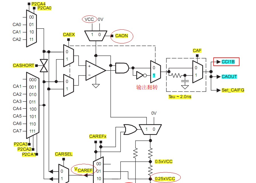
比较通道设置方面,总是感觉越弄越糊涂。下面是用户指南里面写的。
P2CA3 (1) Bits 5-3 Input select. These bits select the - terminal input when CAEX = 0 and the + terminal input when CAEX = 1.
P2CA2 000 No connection
P2CA1
001 CA1
010 CA2
011 CA3
100 CA4
101 CA5
110 CA6
111 CA7
P2CA0 Bit 2 Input select. This bit, together with P2CA4, selects the + terminal input when CAEX = 0 and the - terminal
input when CAEX = 1.
00 No connection
01 CA0
10 CA1
11 CA2我通过这个的理解是比较通道的选择与CAEX有关,就是CAEX决定是同相还是反相端。可是CCS头文件里面是这样定义的:
#define P2CA0 (0x04) /* Comp. A +Terminal Multiplexer */
#define P2CA1 (0x08) /* Comp. A -Terminal Multiplexer */
#define P2CA2 (0x10) /* Comp. A -Terminal Multiplexer */
#define P2CA3 (0x20) /* Comp. A -Terminal Multiplexer */
#define P2CA4 (0x40) /* Comp. A +Terminal Multiplexer */在通道选择同相还是反相端上我始终没搞懂。下面我给个例子:CACTL1=CAON+CAIE+CAREF_2+CAEX+CARSEL;
CACTL2&=~P2CA2;CACTL2=P2CA3+P2CA1+CAF;按用户指南里面的定义应该是参考电压接正端,CA5选择同相端。这样的话不是相当于都在比较器的正端接着吗?应该不是多输入端那种吧?
还有一个问题就是CCS里面的那个测电压的程序,实验效果始终不对。程序如下:
#include <msp430g2553.h>
int main (void)
{
WDTCTL = WDTPW + WDTHOLD; // Stop WDT
P1DIR |= 0x01; // P1.0 output
CACTL2 = P2CA4; // P1.1 = CA1
while (1) // Mainloop
{
Batt_Check();
}
}
void Batt_Check(void)
{
CACTL1 = CAREF_1 + CAON; // 0.25*Vcc on P1.1, Comp. on(这地方为什么说0.25Vcc接到P1.1上啊,不懂???)
i = 16384; // delay
while(i>0)
{
i--;
}
CACTL1 = CARSEL + CAREF_2 + CAREF_1 + CAON; // 0.55V on -, Comp. on
if (CACTL2 & CAOUT)
P1OUT ^= 0x01; // P1.0 toggle
else P1OUT |= 0x01; // P1.0 set
CACTL1 = 0x00; // Disable Comp_A, save power
}
当我把程序写入板子之后,用直流电源给开发板提供可调电源,并按要求在P1.1和地之间接了一个0.1uf的电容。当我用万用表测P1.1电压时,电压总是为0.而且没有程序中说的那种现象。当Vcc电压达到1.5V左右时,LED灯就有了亮度,而且当vcc逐渐增大时。LED灯变亮。这是什么情况。按程序的意思,应该是大于2.2V电压时,P1.0翻转。低于2.2V时灯亮。