This thread has been locked.

If you have a related question, please click the "Ask a related question" button in the top right corner. The newly created question will be automatically linked to this question.

续MSP430FR5969问

Other Parts Discussed in Thread: MSP430FR5969

IO可以工作了,但是想问下为什么需要进行  PM5CTL0 &= ~LOCKLPM5;  设置。

还有,其他引脚在用IO功能时也需要做类似的操作吗 ?

我这样设置P4.6却得不到期望的输出,怎么解决 

  P1OUT &= ~0x01;                 // Clear P1.0 output latch for a defined power-on state
  P1DIR |= 0x01;                  // Set P1.0 to output direction
  P1REN |=0x01;
  P1SEL1=0;
  P1SEL0=0;
 
 
  P4OUT &= ~0x06;                 // Clear P4.6 output latch for a defined power-on state
  P4DIR |= 0x06;                  // Set P4.6 to output direction
  P4REN |=0x06;
  P4SEL1=0;
  P4SEL0=0;
                                  // to activate previously configured port settings

  while(1)
  {
    P1OUT ^= BIT0;                // Toggle LED
     P4OUT ^= BIT6;                // Toggle LED
    __delay_cycles(1000000);
  }

另外能不能再分别给个该单片机的SPI和Uart通信例程。

  • 你好,

    一个一个解决你的问题:

    1.PM5CTL0 &= ~LOCKLPM5

    这个代码你可以去掉,因为这是用来解锁进入LPMx.5后GPIO状态的一句话,在超低功耗应用才用的到。这里加上这句话是怕你程序使能进入了LPMx.5模式。

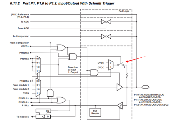
    2.去掉P4REN |= 0x06,这跳语句是使能上拉的意思。默认情况下PxSEL都是为0的,及都默认为GPIO模式。

      P4OUT &= ~0x06;                 // Clear P4.6 output latch for a defined power-on state
      P4DIR |= 0x06;                  // Set P4.6 to output direction
      P4REN |=0x06;
      P4SEL1=0;
      P4SEL0=0;
                                      // to activate previously configured port settings

  • 你好,

    单片机SPI和UART的例程如下,希望对你有帮助:

    /* --COPYRIGHT--,BSD_EX
    * Copyright (c) 2012, Texas Instruments Incorporated
    * All rights reserved.
    *
    * Redistribution and use in source and binary forms, with or without
    * modification, are permitted provided that the following conditions
    * are met:
    *
    * * Redistributions of source code must retain the above copyright
    * notice, this list of conditions and the following disclaimer.
    *
    * * Redistributions in binary form must reproduce the above copyright
    * notice, this list of conditions and the following disclaimer in the
    * documentation and/or other materials provided with the distribution.
    *
    * * Neither the name of Texas Instruments Incorporated nor the names of
    * its contributors may be used to endorse or promote products derived
    * from this software without specific prior written permission.
    *
    * THIS SOFTWARE IS PROVIDED BY THE COPYRIGHT HOLDERS AND CONTRIBUTORS "AS IS"
    * AND ANY EXPRESS OR IMPLIED WARRANTIES, INCLUDING, BUT NOT LIMITED TO,
    * THE IMPLIED WARRANTIES OF MERCHANTABILITY AND FITNESS FOR A PARTICULAR
    * PURPOSE ARE DISCLAIMED. IN NO EVENT SHALL THE COPYRIGHT OWNER OR
    * CONTRIBUTORS BE LIABLE FOR ANY DIRECT, INDIRECT, INCIDENTAL, SPECIAL,
    * EXEMPLARY, OR CONSEQUENTIAL DAMAGES (INCLUDING, BUT NOT LIMITED TO,
    * PROCUREMENT OF SUBSTITUTE GOODS OR SERVICES; LOSS OF USE, DATA, OR PROFITS;
    * OR BUSINESS INTERRUPTION) HOWEVER CAUSED AND ON ANY THEORY OF LIABILITY,
    * WHETHER IN CONTRACT, STRICT LIABILITY, OR TORT (INCLUDING NEGLIGENCE OR
    * OTHERWISE) ARISING IN ANY WAY OUT OF THE USE OF THIS SOFTWARE,
    * EVEN IF ADVISED OF THE POSSIBILITY OF SUCH DAMAGE.
    *
    *******************************************************************************
    *
    * MSP430 CODE EXAMPLE DISCLAIMER
    *
    * MSP430 code examples are self-contained low-level programs that typically
    * demonstrate a single peripheral function or device feature in a highly
    * concise manner. For this the code may rely on the device's power-on default
    * register values and settings such as the clock configuration and care must
    * be taken when combining code from several examples to avoid potential side
    * effects. Also see www.ti.com/grace for a GUI- and www.ti.com/msp430ware
    * for an API functional library-approach to peripheral configuration.
    *
    * --/COPYRIGHT--*/
    //******************************************************************************
    // MSP430F59xx Demo - eUSCI_A0, SPI 3-Wire Master Incremented Data
    //
    // Description: SPI master talks to SPI slave using 3-wire mode. Incrementing
    // data is sent by the master starting at 0x01. Received data is expected to
    // be same as the previous transmission TXData = RXData-1.
    // USCI RX ISR is used to handle communication with the CPU, normally in LPM0.
    // ACLK = 32.768kHz, MCLK = SMCLK = DCO ~1MHz. BRCLK = ACLK/2
    //
    //
    // MSP430FR5969
    // -----------------
    // /|\ | XIN|-
    // | | | 32KHz Crystal
    // ---|RST XOUT|-
    // | |
    // | P2.0|-> Data Out (UCA0SIMO)
    // | |
    // | P2.1|<- Data In (UCA0SOMI)
    // | |
    // | P1.5|-> Serial Clock Out (UCA0CLK)
    //
    // P. Thanigai
    // Texas Instruments Inc.
    // Feb 2012
    // Built with CCS V5.5
    //******************************************************************************
    #include <msp430.h>

    volatile unsigned char RXData = 0;
    volatile unsigned char TXData;

    int main(void)
    {
    WDTCTL = WDTPW | WDTHOLD; // Stop watchdog timer

    // Configure GPIO
    P1SEL1 |= BIT5; // USCI_A0 operation
    P2SEL1 |= BIT0 | BIT1; // USCI_A0 operation
    PJSEL0 |= BIT4 | BIT5; // For XT1

    // Disable the GPIO power-on default high-impedance mode to activate
    // previously configured port settings
    PM5CTL0 &= ~LOCKLPM5;

    // XT1 Setup
    CSCTL0_H = CSKEY >> 8; // Unlock CS registers
    CSCTL1 = DCOFSEL_0; // Set DCO to 1MHz
    CSCTL2 = SELA__LFXTCLK | SELS__DCOCLK | SELM__DCOCLK;
    CSCTL3 = DIVA__1 | DIVS__1 | DIVM__1; // set all dividers
    CSCTL4 &= ~LFXTOFF;
    do
    {
    CSCTL5 &= ~LFXTOFFG; // Clear XT1 fault flag
    SFRIFG1 &= ~OFIFG;
    }while (SFRIFG1&OFIFG); // Test oscillator fault flag
    CSCTL0_H = 0; // Lock CS registers

    // Configure USCI_A0 for SPI operation
    UCA0CTLW0 = UCSWRST; // **Put state machine in reset**
    UCA0CTLW0 |= UCMST | UCSYNC | UCCKPL | UCMSB; // 3-pin, 8-bit SPI master
    // Clock polarity high, MSB
    UCA0CTLW0 |= UCSSEL__ACLK; // ACLK
    UCA0BR0 = 0x02; // /2
    UCA0BR1 = 0; //
    UCA0MCTLW = 0; // No modulation
    UCA0CTLW0 &= ~UCSWRST; // **Initialize USCI state machine**
    UCA0IE |= UCRXIE; // Enable USCI_A0 RX interrupt
    TXData = 0x1; // Holds TX data

    while(1)
    {
    UCA0IE |= UCTXIE;
    __bis_SR_register(LPM0_bits | GIE); // CPU off, enable interrupts
    __delay_cycles(2000); // Delay before next transmission
    TXData++; // Increment transmit data
    }
    }

    #if defined(__TI_COMPILER_VERSION__) || defined(__IAR_SYSTEMS_ICC__)
    #pragma vector=USCI_A0_VECTOR
    __interrupt void USCI_A0_ISR(void)
    #elif defined(__GNUC__)
    void __attribute__ ((interrupt(USCI_A0_VECTOR))) USCI_A0_ISR (void)
    #else
    #error Compiler not supported!
    #endif
    {
    switch(__even_in_range(UCA0IV, USCI_SPI_UCTXIFG))
    {
    case USCI_NONE: break;
    case USCI_SPI_UCRXIFG:
    RXData = UCA0RXBUF;
    UCA0IFG &= ~UCRXIFG;
    __bic_SR_register_on_exit(LPM0_bits); // Wake up to setup next TX
    break;
    case USCI_SPI_UCTXIFG:
    UCA0TXBUF = TXData; // Transmit characters
    UCA0IE &= ~UCTXIE;
    break;
    default: break;
    }
    }

  • UART 例程:

    /* --COPYRIGHT--,BSD_EX
    * Copyright (c) 2012, Texas Instruments Incorporated
    * All rights reserved.
    *
    * Redistribution and use in source and binary forms, with or without
    * modification, are permitted provided that the following conditions
    * are met:
    *
    * * Redistributions of source code must retain the above copyright
    * notice, this list of conditions and the following disclaimer.
    *
    * * Redistributions in binary form must reproduce the above copyright
    * notice, this list of conditions and the following disclaimer in the
    * documentation and/or other materials provided with the distribution.
    *
    * * Neither the name of Texas Instruments Incorporated nor the names of
    * its contributors may be used to endorse or promote products derived
    * from this software without specific prior written permission.
    *
    * THIS SOFTWARE IS PROVIDED BY THE COPYRIGHT HOLDERS AND CONTRIBUTORS "AS IS"
    * AND ANY EXPRESS OR IMPLIED WARRANTIES, INCLUDING, BUT NOT LIMITED TO,
    * THE IMPLIED WARRANTIES OF MERCHANTABILITY AND FITNESS FOR A PARTICULAR
    * PURPOSE ARE DISCLAIMED. IN NO EVENT SHALL THE COPYRIGHT OWNER OR
    * CONTRIBUTORS BE LIABLE FOR ANY DIRECT, INDIRECT, INCIDENTAL, SPECIAL,
    * EXEMPLARY, OR CONSEQUENTIAL DAMAGES (INCLUDING, BUT NOT LIMITED TO,
    * PROCUREMENT OF SUBSTITUTE GOODS OR SERVICES; LOSS OF USE, DATA, OR PROFITS;
    * OR BUSINESS INTERRUPTION) HOWEVER CAUSED AND ON ANY THEORY OF LIABILITY,
    * WHETHER IN CONTRACT, STRICT LIABILITY, OR TORT (INCLUDING NEGLIGENCE OR
    * OTHERWISE) ARISING IN ANY WAY OUT OF THE USE OF THIS SOFTWARE,
    * EVEN IF ADVISED OF THE POSSIBILITY OF SUCH DAMAGE.
    *
    *******************************************************************************
    *
    * MSP430 CODE EXAMPLE DISCLAIMER
    *
    * MSP430 code examples are self-contained low-level programs that typically
    * demonstrate a single peripheral function or device feature in a highly
    * concise manner. For this the code may rely on the device's power-on default
    * register values and settings such as the clock configuration and care must
    * be taken when combining code from several examples to avoid potential side
    * effects. Also see www.ti.com/grace for a GUI- and www.ti.com/msp430ware
    * for an API functional library-approach to peripheral configuration.
    *
    * --/COPYRIGHT--*/
    //******************************************************************************
    // MSP430FR59xx Demo - eUSCI_A0 UART echo at 9600 baud using BRCLK = 8MHz
    //
    // Description: This demo echoes back characters received via a PC serial port.
    // SMCLK/ DCO is used as a clock source and the device is put in LPM3
    // The auto-clock enable feature is used by the eUSCI and SMCLK is turned off
    // when the UART is idle and turned on when a receive edge is detected.
    // Note that level shifter hardware is needed to shift between RS232 and MSP
    // voltage levels.
    //
    // The example code shows proper initialization of registers
    // and interrupts to receive and transmit data.
    // To test code in LPM3, disconnect the debugger.
    //
    // ACLK = VLO, MCLK = DCO = SMCLK = 8MHz
    //
    // MSP430FR5969
    // -----------------
    // RST -| P2.0/UCA0TXD|----> PC (echo)
    // | |
    // | |
    // | P2.1/UCA0RXD|<---- PC
    // | |
    //
    // P. Thanigai
    // Texas Instruments Inc.
    // August 2012
    // Built with IAR Embedded Workbench V5.40 & Code Composer Studio V5.5
    //******************************************************************************
    #include "msp430.h"

    int main(void)
    {
    WDTCTL = WDTPW | WDTHOLD; // Stop Watchdog

    // Configure GPIO
    P2SEL1 |= BIT0 | BIT1; // USCI_A0 UART operation
    P2SEL0 &= ~(BIT0 | BIT1);

    // Disable the GPIO power-on default high-impedance mode to activate
    // previously configured port settings
    PM5CTL0 &= ~LOCKLPM5;

    // Startup clock system with max DCO setting ~8MHz
    CSCTL0_H = CSKEY >> 8; // Unlock clock registers
    CSCTL1 = DCOFSEL_3 | DCORSEL; // Set DCO to 8MHz
    CSCTL2 = SELA__VLOCLK | SELS__DCOCLK | SELM__DCOCLK;
    CSCTL3 = DIVA__1 | DIVS__1 | DIVM__1; // Set all dividers
    CSCTL0_H = 0; // Lock CS registers

    // Configure USCI_A0 for UART mode
    UCA0CTLW0 = UCSWRST; // Put eUSCI in reset
    UCA0CTLW0 |= UCSSEL__SMCLK; // CLK = SMCLK
    // Baud Rate calculation
    // 8000000/(16*9600) = 52.083
    // Fractional portion = 0.083
    // User's Guide Table 21-4: UCBRSx = 0x04
    // UCBRFx = int ( (52.083-52)*16) = 1
    UCA0BR0 = 52; // 8000000/16/9600
    UCA0BR1 = 0x00;
    UCA0MCTLW |= UCOS16 | UCBRF_1;
    UCA0CTLW0 &= ~UCSWRST; // Initialize eUSCI
    UCA0IE |= UCRXIE; // Enable USCI_A0 RX interrupt

    __bis_SR_register(LPM3_bits | GIE); // Enter LPM3, interrupts enabled
    __no_operation(); // For debugger
    }

    #if defined(__TI_COMPILER_VERSION__) || defined(__IAR_SYSTEMS_ICC__)
    #pragma vector=USCI_A0_VECTOR
    __interrupt void USCI_A0_ISR(void)
    #elif defined(__GNUC__)
    void __attribute__ ((interrupt(USCI_A0_VECTOR))) USCI_A0_ISR (void)
    #else
    #error Compiler not supported!
    #endif
    {
    switch(__even_in_range(UCA0IV, USCI_UART_UCTXCPTIFG))
    {
    case USCI_NONE: break;
    case USCI_UART_UCRXIFG:
    while(!(UCA0IFG&UCTXIFG));
    UCA0TXBUF = UCA0RXBUF;
    __no_operation();
    break;
    case USCI_UART_UCTXIFG: break;
    case USCI_UART_UCSTTIFG: break;
    case USCI_UART_UCTXCPTIFG: break;
    }
    }