Part Number: TIDM-02013
Hello, Dear Expert:
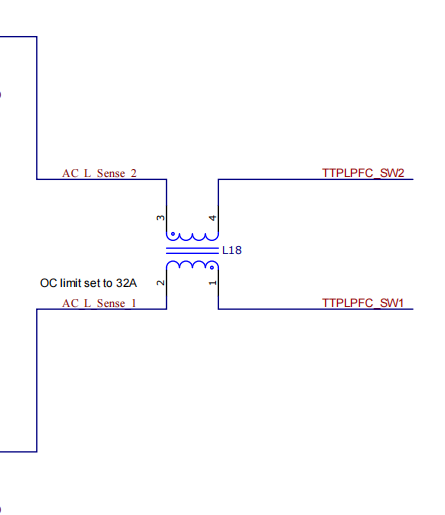
What are the differences between this coupled inductor and conventional discrete inductors? Can it achieve a higher inductance under the same core volume and thus improve power density?
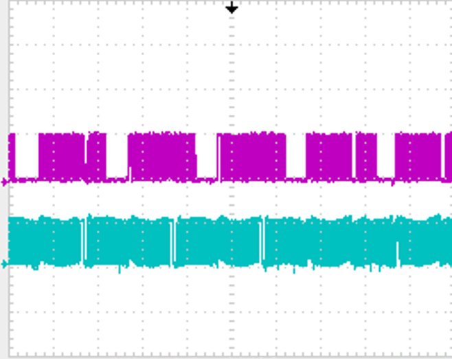
In Lab 3, the PH1 branch operates normally, yet the PH2 branch suffers intermittent drive loss. What are the potential root causes for this fault? Previously, the PFC performance was excellent with an input voltage of 90 V, yielding a power factor above 0.99. The missing drive fault on PH2 only emerged after the input voltage was raised to 200 V.
After proceeding to Lab 4, the Hall-effect sensor on the PH2 branch was damaged. Following replacement of this Hall sensor, the maximum achievable power factor dropped to merely 0.91, and the PH2 drive becomes lost even at 90 V input.
Is it feasible to disconnect one winding of the coupled inductor to test a single branch independently? Are there published papers validating the design of this coupled boost inductor? Can we substitute the coupled inductor with two discrete inductors for subsequent testing? I have exhausted troubleshooting ideas and have no clear direction for further debugging. Your prompt assistance would be highly appreciated.