我直接复制官方的ti\TivaWare_C_Series-2.1.3.156\examples\peripherals\adc下single_ended.c的例程,出现下面的报错
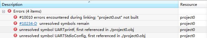
我明明把UARTprintf和UARTStdioConfig这两个头文件进行包含了呀,为什么提示没有定义呢
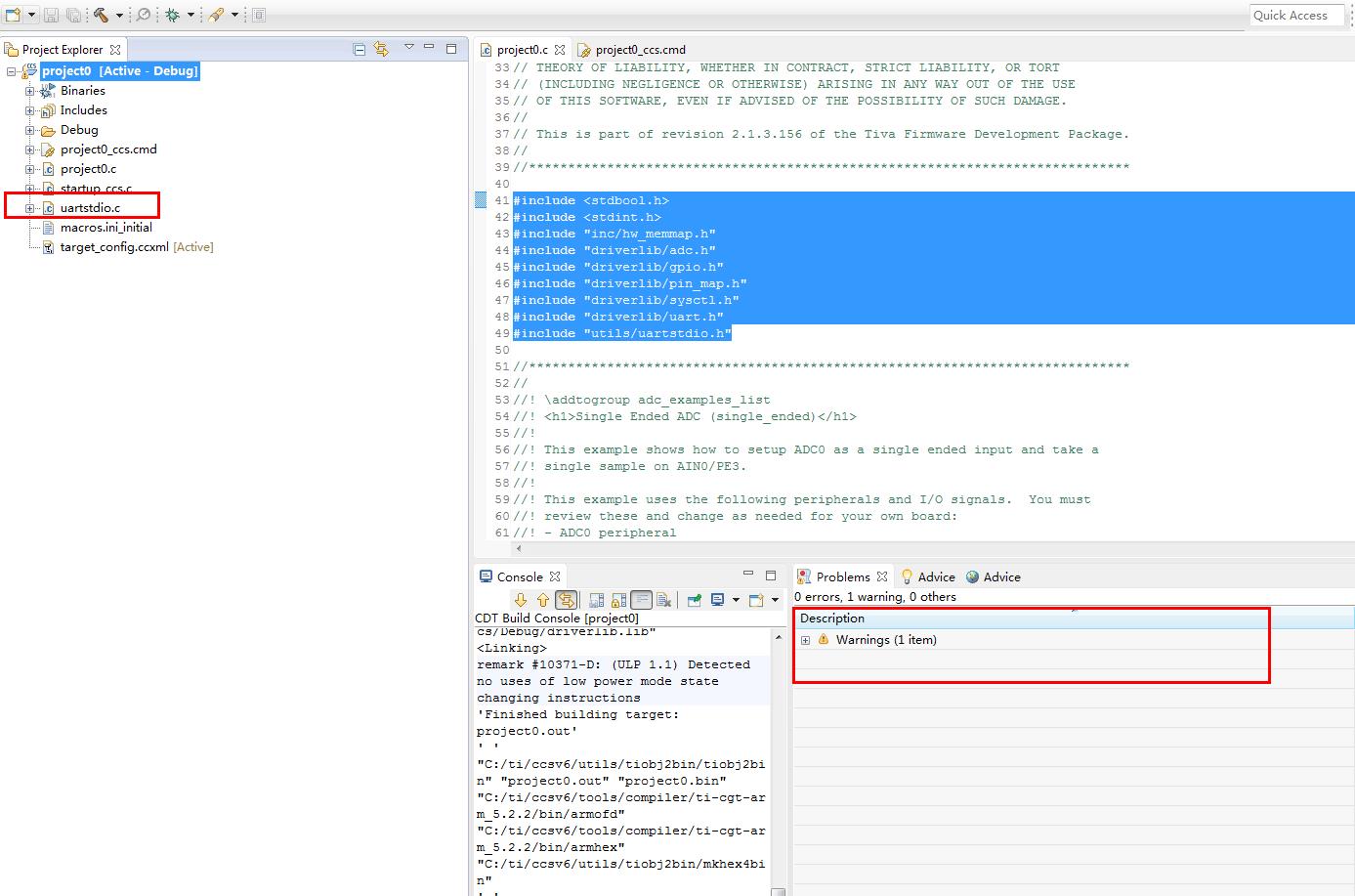
#include <stdbool.h>
#include <stdint.h>
#include "inc/hw_memmap.h"
#include "driverlib/adc.h"
#include "driverlib/gpio.h"
#include "driverlib/pin_map.h"
#include "driverlib/sysctl.h"
#include "driverlib/uart.h"
#include "utils/uartstdio.h"
原来TM4C的库是这样的driverlib下的.c文件,都在.lib文件中已经写入了,直接引用对应的头文件就好了。不用包含相应的.c文件。
.lib的路径位于这里ti\TivaWare_C_Series-2.1.3.156\driverlib\ccs\Debug
而第三方的库,是没有生成.lib这个库文件的,要想使用里面的函数,必须添加相应的.c文件才可以。
我们添加相应的uartstdio.c文件到工程下就好了。