This thread has been locked.

If you have a related question, please click the "Ask a related question" button in the top right corner. The newly created question will be automatically linked to this question.

On the external crystal vibration of M432P401


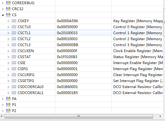
I encountered the following problems when I output M432P401R P4.2. I can't make LFXTCLK_ON 1. I refer to the example of MSP432P401R for the output of 48MHz, but it is still unable to output the external crystal vibration of P4.2.I need your help. I look forward to your reply.thank you

  • https://e2e.ti.com/support/microcontrollers/msp430/f/166/t/622000?tisearch=e2e-quicksearch&keymatch=LFXTCLK_ON
    huixian liu,please check it.
  • msp432p401x_cs_09                              HFXT@48MHz sources MCLK & HSMCLK, output to P4.3 & P4.4

    官方提供的是可以从4.3或者4.4输出,没有给4.2的或许不行。

  • /* --COPYRIGHT--,BSD_EX
     * Copyright (c) 2013, Texas Instruments Incorporated
     * All rights reserved.
     *
     * Redistribution and use in source and binary forms, with or without
     * modification, are permitted provided that the following conditions
     * are met:
     *
     * *  Redistributions of source code must retain the above copyright
     *    notice, this list of conditions and the following disclaimer.
     *
     * *  Redistributions in binary form must reproduce the above copyright
     *    notice, this list of conditions and the following disclaimer in the
     *    documentation and/or other materials provided with the distribution.
     *
     * *  Neither the name of Texas Instruments Incorporated nor the names of
     *    its contributors may be used to endorse or promote products derived
     *    from this software without specific prior written permission.
     *
     * THIS SOFTWARE IS PROVIDED BY THE COPYRIGHT HOLDERS AND CONTRIBUTORS "AS IS"
     * AND ANY EXPRESS OR IMPLIED WARRANTIES, INCLUDING, BUT NOT LIMITED TO,
     * THE IMPLIED WARRANTIES OF MERCHANTABILITY AND FITNESS FOR A PARTICULAR
     * PURPOSE ARE DISCLAIMED. IN NO EVENT SHALL THE COPYRIGHT OWNER OR
     * CONTRIBUTORS BE LIABLE FOR ANY DIRECT, INDIRECT, INCIDENTAL, SPECIAL,
     * EXEMPLARY, OR CONSEQUENTIAL DAMAGES (INCLUDING, BUT NOT LIMITED TO,
     * PROCUREMENT OF SUBSTITUTE GOODS OR SERVICES; LOSS OF USE, DATA, OR PROFITS;
     * OR BUSINESS INTERRUPTION) HOWEVER CAUSED AND ON ANY THEORY OF LIABILITY,
     * WHETHER IN CONTRACT, STRICT LIABILITY, OR TORT (INCLUDING NEGLIGENCE OR
     * OTHERWISE) ARISING IN ANY WAY OUT OF THE USE OF THIS SOFTWARE,
     * EVEN IF ADVISED OF THE POSSIBILITY OF SUCH DAMAGE.
     *
     *******************************************************************************
     *
     *                       MSP432 CODE EXAMPLE DISCLAIMER
     *
     * MSP432 code examples are self-contained low-level programs that typically
     * demonstrate a single peripheral function or device feature in a highly
     * concise manner. For this the code may rely on the device's power-on default
     * register values and settings such as the clock configuration and care must
     * be taken when combining code from several examples to avoid potential side
     * effects. Also see http://www.ti.com/tool/mspdriverlib for an API functional
     * library & https://dev.ti.com/pinmux/ for a GUI approach to peripheral configuration.
     *
     * --/COPYRIGHT--*/
    //******************************************************************************
    //   MSP432P401 Demo - HFXT@48MHz sources MCLK & HSMCLK, output to P4.3 & P4.4
    //
    //   Description: Proper device configuration to enable operation at MCLK=48MHz
    //   including:
    //   1. Configure VCORE level to 1
    //   2. Configure flash wait-state to 1
    //   3. Configure HFXT sourced by 48MHz XTAL
    //   4. Source MCLK & HSMCLK from HFXT
    //
    //   After configuration is complete, MCLK & HSMCLK are output to port pins P4.3.
    //
    //                MSP432P401x
    //             -----------------
    //         /|\|                 |
    //          | |                 |
    //          --|RST              |
    //            |             P4.3|----> MCLK
    //            |             P4.4|----> HSMCLK
    //            |                 |
    //            |             PJ.2|------
    //            |                 |     |
    //            |                 |    HFXT @ 48MHz
    //            |                 |     |
    //            |             PJ.3|------
    //
    //   William Goh
    //   Texas Instruments Inc.
    //   June 2016 (updated) | July 2015 (created)
    //   Built with CCSv6.1, IAR, Keil, GCC
    //******************************************************************************
    #include "msp.h"
    #include "stdint.h"
    
    void error(void);
    
    int main(void)
    {
        volatile uint32_t i;
        uint32_t currentPowerState;
    
        WDT_A->CTL = WDT_A_CTL_PW |             // Stop WDT
                     WDT_A_CTL_HOLD;
    
        P1->DIR |= BIT0;
    
        /* NOTE: This example assumes the default power state is AM0_LDO.
         * Refer to  msp432p401x_pcm_0x code examples for more complete PCM operations
         * to exercise various power state transitions between active modes.
         */
    
        /* Step 1: Transition to VCORE Level 1: AM0_LDO --> AM1_LDO */
    
        /* Get current power state, if it's not AM0_LDO, error out */
        currentPowerState = PCM->CTL0 & PCM_CTL0_CPM_MASK;
        if (currentPowerState != PCM_CTL0_CPM_0)
            error();
    
        while ((PCM->CTL1 & PCM_CTL1_PMR_BUSY));
        PCM->CTL0 = PCM_CTL0_KEY_VAL | PCM_CTL0_AMR_1;
        while ((PCM->CTL1 & PCM_CTL1_PMR_BUSY));
        if (PCM->IFG & PCM_IFG_AM_INVALID_TR_IFG)
            error();                            // Error if transition was not successful
        if ((PCM->CTL0 & PCM_CTL0_CPM_MASK) != PCM_CTL0_CPM_1)
            error();                            // Error if device is not in AM1_LDO mode
    
        /* Step 2: Configure Flash wait-state to 1 for both banks 0 & 1 */
        FLCTL->BANK0_RDCTL = (FLCTL->BANK0_RDCTL & ~(FLCTL_BANK0_RDCTL_WAIT_MASK)) |
                FLCTL_BANK0_RDCTL_WAIT_1;
        FLCTL->BANK1_RDCTL = (FLCTL->BANK0_RDCTL & ~(FLCTL_BANK1_RDCTL_WAIT_MASK)) |
                FLCTL_BANK1_RDCTL_WAIT_1 ;
    
        /* Step 3: Configure HFXT to use 48MHz crystal, source to MCLK & HSMCLK*/
    
    
        PJ->SEL0 |= BIT2 | BIT3;                // Configure PJ.2/3 for HFXT function
        PJ->SEL1 &= ~(BIT2 | BIT3);
    
        CS->KEY = CS_KEY_VAL ;                  // Unlock CS module for register access
        CS->CTL2 |= CS_CTL2_HFXT_EN | CS_CTL2_HFXTFREQ_6 | CS_CTL2_HFXTDRIVE;
        while(CS->IFG & CS_IFG_HFXTIFG)
            CS->CLRIFG |= CS_CLRIFG_CLR_HFXTIFG;
    
        /* Select MCLK & HSMCLK = HFXT, no divider */
        CS->CTL1 = CS->CTL1 & ~(CS_CTL1_SELM_MASK | CS_CTL1_DIVM_MASK | CS_CTL1_SELS_MASK | CS_CTL1_DIVHS_MASK) |
                CS_CTL1_SELM__HFXTCLK | CS_CTL1_SELS__HFXTCLK;
    
        CS->KEY = 0;                            // Lock CS module from unintended accesses
    
        /* Step 4: Output MCLK to port pin to demonstrate 48MHz operation */
        P4->DIR |= BIT3 | BIT4;
        P4->SEL0 |=BIT3 | BIT4;                 // Output MCLK
        P4->SEL1 &= ~(BIT3 | BIT4);
    
        while (1)                               // continuous loop
        {
            P1->OUT ^= BIT0;                    // Blink P1.0 LED
            for (i = 200000; i > 0; i--);       // Delay
        }
    }
    
    void error(void)
    {
        volatile uint32_t i;
    
        while (1)
        {
            P1->OUT ^= BIT0;
            for(i = 20000; i> 0; i--);          // Blink LED forever
        }
    }