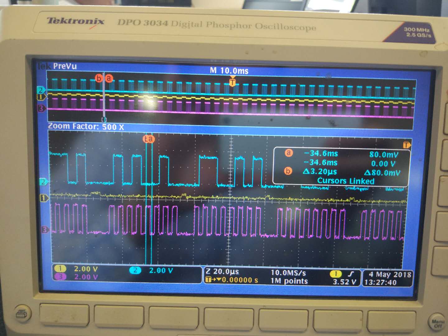
TM4C123GXL ssi0初始化后,观测CLK、FSS、MOSI的时序发现是正确的,但是FSS的信号电平只有0.2V的高低电平变化,而CLK 和MOSI的电平是3.3V。为什么会出现这种现象?而因脚上没有任何外接上下拉电阻和其他电路,有谁遇到过这样的情况吗?难道GPIOA[2:5]的配置哪里不对吗?下面是SSI0的初始化函数。
//
// The SSI0 peripheral must be enabled for use.
//
SysCtlPeripheralEnable(SYSCTL_PERIPH_SSI0);
//
// For this example SSI0 is used with PortA[5:2]. The actual port and pins
// used may be different on your part, consult the data sheet for more
// information. GPIO port A needs to be enabled so these pins can be used.
// TODO: change this to whichever GPIO port you are using.
//
SysCtlPeripheralEnable(SYSCTL_PERIPH_GPIOA);
//
// Configure the pin muxing for SSI0 functions on port A2, A3, A4, and A5.
// This step is not necessary if your part does not support pin muxing.
// TODO: change this to select the port/pin you are using.
//
GPIOPinConfigure(GPIO_PA2_SSI0CLK);
GPIOPinConfigure(GPIO_PA3_SSI0FSS);
GPIOPinConfigure(GPIO_PA4_SSI0RX);
GPIOPinConfigure(GPIO_PA5_SSI0TX);
//
// Configure the GPIO settings for the SSI pins. This function also gives
// control of these pins to the SSI hardware. Consult the data sheet to
// see which functions are allocated per pin.
// The pins are assigned as follows:
// PA5 - SSI0Tx
// PA4 - SSI0Rx
// PA3 - SSI0Fss
// PA2 - SSI0CLK
// TODO: change this to select the port/pin you are using.
//
GPIOPinTypeSSI(GPIO_PORTA_BASE, GPIO_PIN_5 | GPIO_PIN_4 | GPIO_PIN_3 | GPIO_PIN_2);
//
// Configure and enable the SSI port for SPI master mode. Use SSI0,
// system clock supply, idle clock level low and active low clock in
// freescale SPI mode, master mode, 1MHz SSI frequency, and 8-bit data.
// For SPI mode, you can set the polarity of the SSI clock when the SSI
// unit is idle. You can also configure what clock edge you want to
// capture data on. Please reference the datasheet for more information on
// the different SPI modes.
//
SSIConfigSetExpClk(SSI0_BASE, SysCtlClockGet(), SSI_FRF_MOTO_MODE_0,
SSI_MODE_MASTER, 200000, 8);
//
// Enable the SSI0 interrupt.
//
ROM_IntEnable(INT_SSI0);
SSIIntEnable(SSI0_BASE,SSI_RXFF);
// HWREG(SSI0_BASE + SSI_O_CR1) |= SSI_CR1_LBM;
// HWREG(SSI0_BASE + SSI_O_CR1) |= SSI_CR1_SSE;
//
// Enable the SSI0 module.
//
SSIEnable(SSI0_BASE);
//
// Enable processor interrupts.
//
ROM_IntMasterEnable();