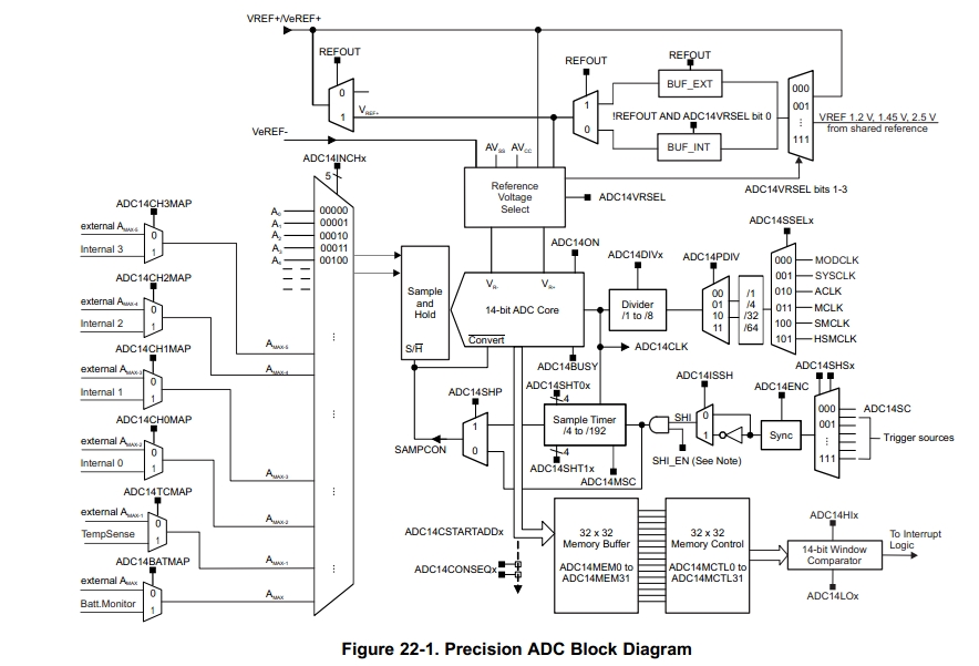
这几天尝试玩了一下MSP432P401R的ADC采样外设。MSP432P401R这款单片机的ADC是14位精度,通过软件过采样可以支持达到16位精度,高达1Msps采样速率。有单端和差分方式输入,2个窗口比较器,有32个采样通道,其中内部通道6个。有3个内部电压基准:1.2V,1.45V,2.5V。
下图是ADC框图:
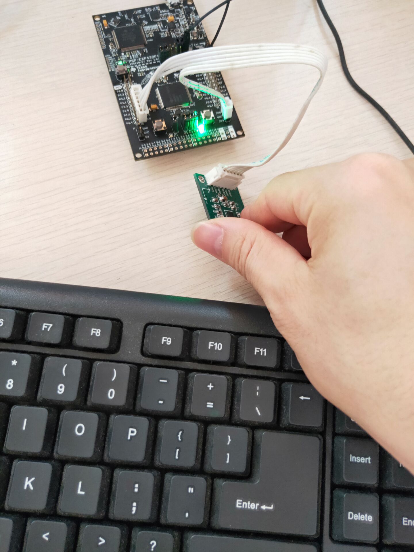
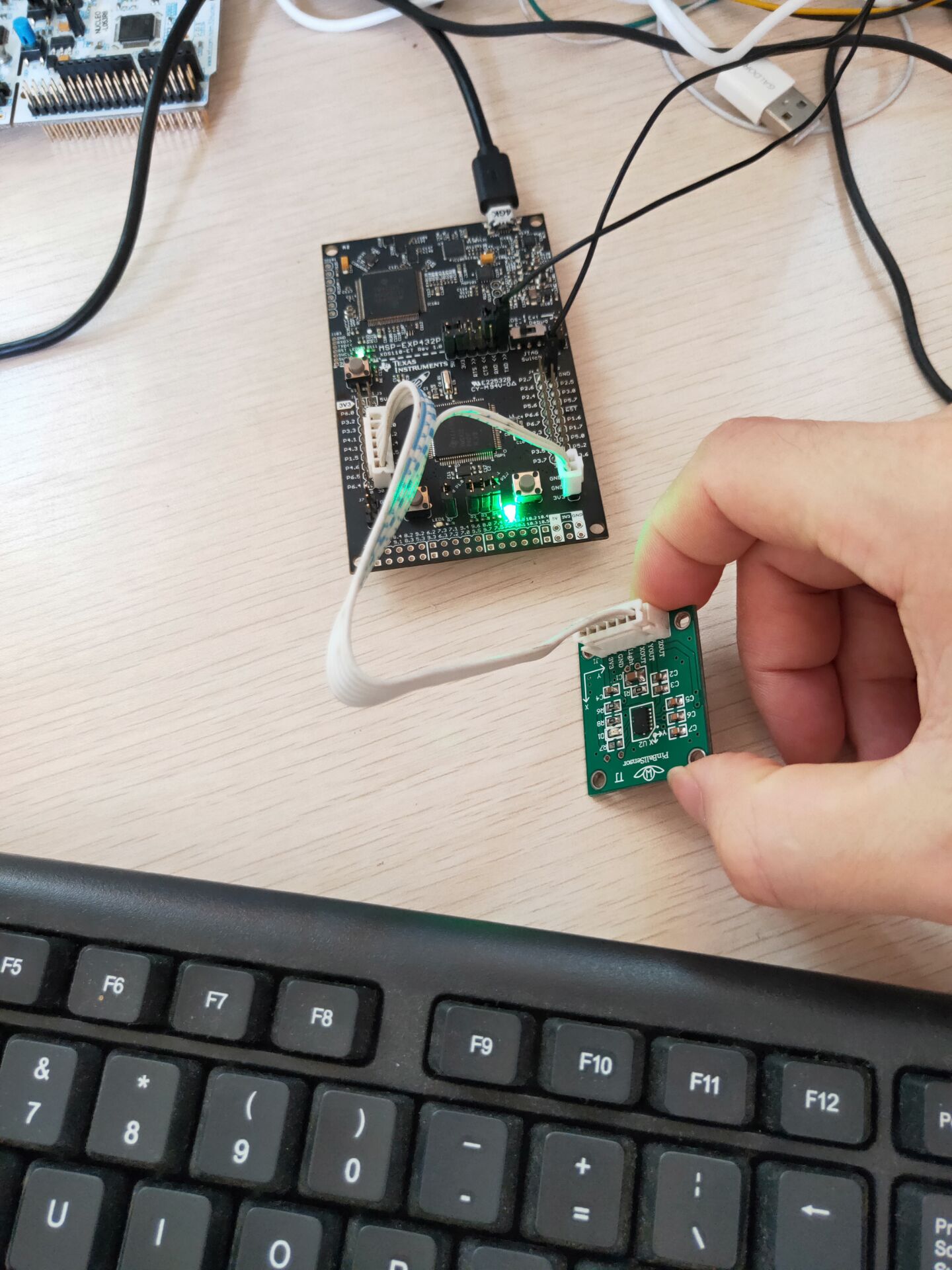
正好自己有用模拟型加速度传感器MMA7361,以前项目做震动和倾斜检测用的。这次正好拿来测试一下MSP432P401R的ADC功能。MMA7361有XYZ轴模拟电压,需要3路AD采样。
硬件连接:
Z轴--->P5.5(A0)
Y轴--->P5.4(A1)
X轴--->P4.7(A6)
选择这3个引脚是因为板子上3个引脚正好在一起,方便连接。
配置ADC为3个通道连续循环转换,使用软件触发采样源,基准电压使用AVCC=3.3V。程序实现简单的倾斜和震动检测,当发生倾斜或者震动时点亮LED灯。可以调整感应灵敏度阈值。
//*****************************************************************************
//
// Copyright (C) 2014 Texas Instruments Incorporated - http://www.ti.com/
//
// Redistribution and use in source and binary forms, with or without
// modification, are permitted provided that the following conditions
// are met:
//
//  Redistributions of source code must retain the above copyright
//  notice, this list of conditions and the following disclaimer.
//
//  Redistributions in binary form must reproduce the above copyright
//  notice, this list of conditions and the following disclaimer in the
//  documentation and/or other materials provided with the
//  distribution.
//
//  Neither the name of Texas Instruments Incorporated nor the names of
//  its contributors may be used to endorse or promote products derived
//  from this software without specific prior written permission.
//
// THIS SOFTWARE IS PROVIDED BY THE COPYRIGHT HOLDERS AND CONTRIBUTORS
// "AS IS" AND ANY EXPRESS OR IMPLIED WARRANTIES, INCLUDING, BUT NOT
// LIMITED TO, THE IMPLIED WARRANTIES OF MERCHANTABILITY AND FITNESS FOR
// A PARTICULAR PURPOSE ARE DISCLAIMED. IN NO EVENT SHALL THE COPYRIGHT
// OWNER OR CONTRIBUTORS BE LIABLE FOR ANY DIRECT, INDIRECT, INCIDENTAL,
// SPECIAL, EXEMPLARY, OR CONSEQUENTIAL DAMAGES (INCLUDING, BUT NOT
// LIMITED TO, PROCUREMENT OF SUBSTITUTE GOODS OR SERVICES; LOSS OF USE,
// DATA, OR PROFITS; OR BUSINESS INTERRUPTION) HOWEVER CAUSED AND ON ANY
// THEORY OF LIABILITY, WHETHER IN CONTRACT, STRICT LIABILITY, OR TORT
// (INCLUDING NEGLIGENCE OR OTHERWISE) ARISING IN ANY WAY OUT OF THE USE
// OF THIS SOFTWARE, EVEN IF ADVISED OF THE POSSIBILITY OF SUCH DAMAGE.
//
// main.c - MSP-EXP432P401R Out Of Box Demo
//
//          Blinks RGB LED at 1Hz. Button S1 allows taps-to-beat that will
//          match the RGB blink frequency to the tap frequency. Button S2
//          cycles through 4 different color states, R/G/B/RandomColor, each
//          with its saved blink frequency.
//
//          The demo also accepts UART data from the Out Of Box GUI that
//          allows changing the RGB LED's color with a color wheel and
//          frequency by entering desired beats-per-minute
//
//****************************************************************************

#include <ti/devices/msp432p4xx/driverlib/driverlib.h>
#include <time.h>
#include <stdlib.h>

#define MCLK_FREQUENCY 3000000

int sysTickCount = 0;       // Counts # of SysTick interrupts since last tap


/* UART Configuration Parameter. These are the configuration parameters to
 * make the eUSCI A UART module to operate with a 115200 baud rate. These
 * values were calculated using the online calculator that TI provides
 * at:
 *processors.wiki.ti.com/.../USCI_UART_Baud_Rate_Gen_Mode_Selection
 */
const eUSCI_UART_Config uartConfig =
{
        EUSCI_A_UART_CLOCKSOURCE_SMCLK,          // SMCLK Clock Source
        26,                                      // BRDIV = 26
        0,                                       // UCxBRF = 0
        0,                                       // UCxBRS = 0
        EUSCI_A_UART_NO_PARITY,                  // No Parity
        EUSCI_A_UART_LSB_FIRST,                  // MSB First
        EUSCI_A_UART_ONE_STOP_BIT,               // One stop bit
        EUSCI_A_UART_MODE,                       // UART mode
        EUSCI_A_UART_LOW_FREQUENCY_BAUDRATE_GENERATION  // Low Frequency Mode
};

/* Statics */
static volatile uint16_t curADCResult;
static volatile float normalizedADCRes;
uint8_t		AdcValue[16];
uint32_t	tickcnt;


uint16_t	ADC_x[5];
uint16_t	ADC_y[5];
uint16_t	ADC_z[5];
uint16_t	ADC_x_cnt = 0;
uint16_t	ADC_y_cnt = 0;
uint16_t	ADC_z_cnt = 0;

uint16_t	ADC_x_cen = 0;	//ˮƽֵ
uint16_t	ADC_y_cen = 0;	//ˮƽֵ
uint16_t	ADC_z_cen = 0;	//ˮƽֵ

uint16_t	ADC_x_cur = 0;	//µ±Ç°Öµ
uint16_t	ADC_y_cur = 0;	//µ±Ç°Öµ
uint16_t	ADC_z_cur = 0;	//µ±Ç°Öµ

uint16_t SortValue(uint16_t *buf, uint16_t len)
{
	uint16_t	i,j;
	uint16_t	temp;

	if(len < 3)	return 0;
	for(i=1; i<len; i++)
	{
		for(j = 0; j < (len-i); j++)
		{
			if(buf[j] > buf[j+1])
			{
				temp = buf[j];
				buf[j] = buf[j+1];
				buf[j+1] = temp;
			}
		}
	}
	temp = 0;
	for(i=1;i<(len-1);i++)
	{
		temp += buf[i];
	}
	temp /= (len-2);
	return temp;

}
/*
 * Main function
 */
int main(void)
{
    /* Halting WDT and disabling master interrupts */
    MAP_WDT_A_holdTimer();
    MAP_Interrupt_disableMaster();

    /* Initializing Variables */
    curADCResult = 0;
	AdcValue[0] = 0xff;
	AdcValue[1] = 0xff;
	AdcValue[2] = 0;
	AdcValue[3] = 0;
	AdcValue[4] = 0;
	AdcValue[5] = 0;
	AdcValue[6] = 0;
	AdcValue[7] = 0;
	AdcValue[8] = 0;
	AdcValue[9] = 0;


    /* Set the core voltage level to VCORE1 */
    MAP_PCM_setCoreVoltageLevel(PCM_VCORE1);

    /* Set 2 flash wait states for Flash bank 0 and 1*/
    MAP_FlashCtl_setWaitState(FLASH_BANK0, 2);
    MAP_FlashCtl_setWaitState(FLASH_BANK1, 2);

    /* Initialize main clock to 3MHz */
    MAP_CS_setDCOCenteredFrequency(CS_DCO_FREQUENCY_3);
    MAP_CS_initClockSignal(CS_MCLK, CS_DCOCLK_SELECT, CS_CLOCK_DIVIDER_1 );
    MAP_CS_initClockSignal(CS_HSMCLK, CS_DCOCLK_SELECT, CS_CLOCK_DIVIDER_1 );
    MAP_CS_initClockSignal(CS_SMCLK, CS_DCOCLK_SELECT, CS_CLOCK_DIVIDER_1 );


    /* Confinguring P1.1 & P1.4 as an input and enabling interrupts */
    MAP_GPIO_setAsInputPinWithPullUpResistor(GPIO_PORT_P1, GPIO_PIN1 | GPIO_PIN4);
    MAP_GPIO_clearInterruptFlag(GPIO_PORT_P1, GPIO_PIN1 | GPIO_PIN4);
    MAP_GPIO_enableInterrupt(GPIO_PORT_P1, GPIO_PIN1 | GPIO_PIN4);
    MAP_GPIO_interruptEdgeSelect(GPIO_PORT_P1, GPIO_PIN1 | GPIO_PIN4, GPIO_HIGH_TO_LOW_TRANSITION);


    /* Selecting P1.2 and P1.3 in UART mode */
    MAP_GPIO_setAsPeripheralModuleFunctionInputPin(GPIO_PORT_P1,
        GPIO_PIN2 | GPIO_PIN3, GPIO_PRIMARY_MODULE_FUNCTION);
    /* Configuring UART Module */
    MAP_UART_initModule(EUSCI_A0_BASE, &uartConfig);
    /* Enable UART module */
    MAP_UART_enableModule(EUSCI_A0_BASE);


	//P1.0,P2.0,P2.1,P2.2
    MAP_GPIO_setAsOutputPin(GPIO_PORT_P1, GPIO_PIN0);
    MAP_GPIO_setAsOutputPin(GPIO_PORT_P2, GPIO_PIN0 | GPIO_PIN1 | GPIO_PIN2);

    /* Enabling the FPU for floating point operation */
    MAP_FPU_enableModule();
    MAP_FPU_enableLazyStacking();

    //![Single Sample Mode Configure]
    /* Initializing ADC (MCLK/1/1) */
    MAP_ADC14_enableModule();
    MAP_ADC14_initModule(ADC_CLOCKSOURCE_MCLK, ADC_PREDIVIDER_1, ADC_DIVIDER_4,0);

    /* Configuring GPIOs (5.5 A0)(5.4 A1) */
    MAP_GPIO_setAsPeripheralModuleFunctionInputPin( GPIO_PORT_P5, GPIO_PIN4|GPIO_PIN5,
													GPIO_TERTIARY_MODULE_FUNCTION);
	//(4.7 A6)
	MAP_GPIO_setAsPeripheralModuleFunctionInputPin(GPIO_PORT_P4,GPIO_PIN7,
													GPIO_TERTIARY_MODULE_FUNCTION);

    /* Configuring ADC Memory */
    MAP_ADC14_configureMultiSequenceMode(ADC_MEM0,ADC_MEM2, true);

    MAP_ADC14_configureConversionMemory(ADC_MEM0, ADC_VREFPOS_AVCC_VREFNEG_VSS,
										ADC_INPUT_A0, false);
    MAP_ADC14_configureConversionMemory(ADC_MEM1, ADC_VREFPOS_AVCC_VREFNEG_VSS,
										ADC_INPUT_A1, false);
	MAP_ADC14_configureConversionMemory(ADC_MEM2, ADC_VREFPOS_AVCC_VREFNEG_VSS,
										ADC_INPUT_A6, false);
    /* Configuring Sample Timer */
    MAP_ADC14_enableSampleTimer(ADC_MANUAL_ITERATION);

    /* Enabling/Toggling Conversion */
    MAP_ADC14_enableConversion();
    //![Single Sample Mode Configure]


    /* Configure and enable SysTick 1ms*/
    MAP_SysTick_setPeriod(1500);
    MAP_SysTick_enableModule();
    MAP_SysTick_enableInterrupt();


	/* Enabling interrupts */
    MAP_GPIO_clearInterruptFlag(GPIO_PORT_P1, GPIO_PIN1 | GPIO_PIN4);
    MAP_UART_enableInterrupt(EUSCI_A0_BASE, EUSCI_A_UART_RECEIVE_INTERRUPT);
    MAP_ADC14_enableInterrupt(ADC_INT0 | ADC_INT1 | ADC_INT2);

    MAP_Interrupt_enableInterrupt(INT_EUSCIA0);
    MAP_Interrupt_enableInterrupt(INT_PORT1);
    MAP_Interrupt_enableInterrupt(INT_ADC14);

    MAP_Interrupt_enableMaster();

    /* Main while loop */
    MAP_ADC14_toggleConversionTrigger();


	tickcnt = sysTickCount;
    while(1)
    {
		if((sysTickCount -  tickcnt) > 10)
		{
			MAP_UART_transmitData(EUSCI_A0_BASE, AdcValue[0]);
			MAP_UART_transmitData(EUSCI_A0_BASE, AdcValue[1]);
			MAP_UART_transmitData(EUSCI_A0_BASE, AdcValue[2]);
			MAP_UART_transmitData(EUSCI_A0_BASE, AdcValue[3]);
			MAP_UART_transmitData(EUSCI_A0_BASE, AdcValue[4]);
			MAP_UART_transmitData(EUSCI_A0_BASE, AdcValue[5]);
			MAP_UART_transmitData(EUSCI_A0_BASE, AdcValue[6]);
			MAP_UART_transmitData(EUSCI_A0_BASE, AdcValue[7]);
			MAP_UART_transmitData(EUSCI_A0_BASE, AdcValue[8]);
			MAP_UART_transmitData(EUSCI_A0_BASE, AdcValue[9]);

			if((ADC_x_cur > (ADC_x_cen + 0x800)) ||
				((ADC_x_cur + 0x800) < (ADC_x_cen)))
			{
				MAP_GPIO_setOutputHighOnPin(GPIO_PORT_P2, GPIO_PIN0);
			}else
			{
				MAP_GPIO_setOutputLowOnPin(GPIO_PORT_P2, GPIO_PIN0);
			}

			if((ADC_y_cur > (ADC_y_cen + 0x800)) ||
				((ADC_y_cur + 0x800) < (ADC_y_cen)))
			{
				MAP_GPIO_setOutputHighOnPin(GPIO_PORT_P2, GPIO_PIN1);
			}else
			{
				MAP_GPIO_setOutputLowOnPin(GPIO_PORT_P2, GPIO_PIN1);
			}

			if((ADC_z_cur > (ADC_z_cen + 0x800)) ||
				((ADC_z_cur + 0x800) < (ADC_z_cen)))
			{
				MAP_GPIO_setOutputHighOnPin(GPIO_PORT_P2, GPIO_PIN2);
			}else
			{
				MAP_GPIO_setOutputLowOnPin(GPIO_PORT_P2, GPIO_PIN2);
			}

			MAP_GPIO_setOutputLowOnPin(GPIO_PORT_P1, GPIO_PIN0);

			tickcnt = sysTickCount;
		}

//        MAP_PCM_gotoLPM0();
    }
}

/*
 * Port 1 interrupt handler. This handler is called whenever switches attached
 * to P1.1 (S1) and P1.4 (S2) are pressed.
 */
void PORT1_IRQHandler(void)
{
//    newTick = MAP_SysTick_getValue();
    uint32_t status = MAP_GPIO_getEnabledInterruptStatus(GPIO_PORT_P1);
    MAP_GPIO_clearInterruptFlag(GPIO_PORT_P1, status);

    /* Handles S1 button press */
    if (status & GPIO_PIN1)
    {
		MAP_GPIO_setOutputHighOnPin(GPIO_PORT_P1, GPIO_PIN0);

		ADC_x_cen = ((AdcValue[6]<<8) | (AdcValue[7]));
		ADC_y_cen = ((AdcValue[4]<<8) | (AdcValue[5]));
		ADC_z_cen = ((AdcValue[2]<<8) | (AdcValue[3]));
    }
    /* Handles S2 button press */
    if (status & GPIO_PIN4)
    {

    }
}

 //![Single Sample Result]
/* ADC Interrupt Handler. This handler is called whenever there is a conversion
 * that is finished for ADC_MEM0.
 */

void ADC14_IRQHandler(void)
{
    uint64_t 	status = MAP_ADC14_getEnabledInterruptStatus();
    MAP_ADC14_clearInterruptFlag(status);

    if (ADC_INT0 & status)
    {
        curADCResult = MAP_ADC14_getResult(ADC_MEM0);
        normalizedADCRes = (curADCResult * 3.3) / 16384;

		ADC_z[ADC_z_cnt++] = curADCResult;
		if(ADC_z_cnt == 5)
		{
			ADC_z_cnt = 0;
			ADC_z_cur = SortValue(ADC_z, 5);
			AdcValue[2] = ADC_z_cur>>8;
			AdcValue[3] = ADC_z_cur&0xff;
		}

        MAP_ADC14_toggleConversionTrigger();
    }

    if (ADC_INT1 & status)
    {
        curADCResult = MAP_ADC14_getResult(ADC_MEM1);
        normalizedADCRes = (curADCResult * 3.3) / 16384;

		ADC_y[ADC_y_cnt++] = curADCResult;
		if(ADC_y_cnt == 5)
		{
			ADC_y_cnt = 0;
			ADC_y_cur = SortValue(ADC_y, 5);
			AdcValue[4] = ADC_y_cur>>8;
			AdcValue[5] = ADC_y_cur&0xff;
		}

        MAP_ADC14_toggleConversionTrigger();
    }

    if (ADC_INT2 & status)
    {
        curADCResult = MAP_ADC14_getResult(ADC_MEM2);
        normalizedADCRes = (curADCResult * 3.3) / 16384;

		ADC_x[ADC_x_cnt++] = curADCResult;
		if(ADC_x_cnt == 5)
		{
			ADC_x_cnt = 0;
			ADC_x_cur = SortValue(ADC_x, 5);
			AdcValue[6] = ADC_x_cur>>8;
			AdcValue[7] = ADC_x_cur&0xff;
		}

        MAP_ADC14_toggleConversionTrigger();
    }

}
/*
 * SysTick interrupt handler. This handler toggles RGB LED on/off.
 */
void SysTick_Handler(void)
{
	sysTickCount++;

}

/*
 * EUSCI A0 UART interrupt handler. Receives data from GUI and sets LED color/blink frequency
 */
void EUSCIA0_IRQHandler(void)
{
    int receiveByte = UCA0RXBUF;

    /* Send acknowledgement to the GUI */
    MAP_UART_transmitData(EUSCI_A0_BASE, 'A');
	MAP_UART_transmitData(EUSCI_A0_BASE, receiveByte);


}