If you have a related question, please click the "Ask a related question" button in the top right corner. The newly created question will be automatically linked to this question.
while(ROM_UARTBusy(UART0_BASE))//add by susan { // delay here until transmission is complete }
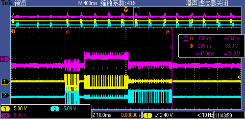
可以成功发送,代码如下
//*****************************************************************************
//
// uart_echo.c - Example for reading data from and writing data to the UART in
//               an interrupt driven fashion.
//
// Copyright (c) 2012-2017 Texas Instruments Incorporated.  All rights reserved.
// Software License Agreement
//
// Texas Instruments (TI) is supplying this software for use solely and
// exclusively on TI's microcontroller products. The software is owned by
// TI and/or its suppliers, and is protected under applicable copyright
// laws. You may not combine this software with "viral" open-source
// software in order to form a larger program.
//
// THIS SOFTWARE IS PROVIDED "AS IS" AND WITH ALL FAULTS.
// NO WARRANTIES, WHETHER EXPRESS, IMPLIED OR STATUTORY, INCLUDING, BUT
// NOT LIMITED TO, IMPLIED WARRANTIES OF MERCHANTABILITY AND FITNESS FOR
// A PARTICULAR PURPOSE APPLY TO THIS SOFTWARE. TI SHALL NOT, UNDER ANY
// CIRCUMSTANCES, BE LIABLE FOR SPECIAL, INCIDENTAL, OR CONSEQUENTIAL
// DAMAGES, FOR ANY REASON WHATSOEVER.
//
// This is part of revision 2.1.4.178 of the EK-TM4C123GXL Firmware Package.
//
//*****************************************************************************

#include <stdint.h>
#include <stdbool.h>
#include "inc/hw_ints.h"
#include "inc/hw_memmap.h"
#include "driverlib/debug.h"
#include "driverlib/fpu.h"
#include "driverlib/gpio.h"
#include "driverlib/interrupt.h"
#include "driverlib/pin_map.h"
#include "driverlib/rom.h"
#include "driverlib/sysctl.h"
#include "driverlib/uart.h"

//*****************************************************************************
//
//! \addtogroup example_list
//! <h1>UART Echo (uart_echo)</h1>
//!
//! This example application utilizes the UART to echo text.  The first UART
//! (connected to the USB debug virtual serial port on the evaluation board)
//! will be configured in 115,200 baud, 8-n-1 mode.  All characters received on
//! the UART are transmitted back to the UART.
//
//*****************************************************************************

//*****************************************************************************
//
// The error routine that is called if the driver library encounters an error.
//
//*****************************************************************************
#ifdef DEBUG
void
__error__(char *pcFilename, uint32_t ui32Line)
{
}
#endif

//*****************************************************************************
//
// The UART interrupt handler.
//
//*****************************************************************************
void
UARTIntHandler(void)
{
    uint32_t ui32Status;

    //
    // Get the interrrupt status.
    //
    ui32Status = ROM_UARTIntStatus(UART0_BASE, true);

    //
    // Clear the asserted interrupts.
    //
    ROM_UARTIntClear(UART0_BASE, ui32Status);

    //
    // Loop while there are characters in the receive FIFO.
    //
    while(ROM_UARTCharsAvail(UART0_BASE))
    {
        //
        // Read the next character from the UART and write it back to the UART.
        //
        ROM_UARTCharPutNonBlocking(UART0_BASE,
                                   ROM_UARTCharGetNonBlocking(UART0_BASE));

        //
        // Blink the LED to show a character transfer is occuring.
        //
        GPIOPinWrite(GPIO_PORTF_BASE, GPIO_PIN_2, GPIO_PIN_2);

        //
        // Delay for 1 millisecond.  Each SysCtlDelay is about 3 clocks.
        //
        SysCtlDelay(SysCtlClockGet() / (1000 * 3));

        //
        // Turn off the LED
        //
        GPIOPinWrite(GPIO_PORTF_BASE, GPIO_PIN_2, 0);

    }
}

//*****************************************************************************
//
// Send a string to the UART.
//
//*****************************************************************************
void
UARTSend(const uint8_t *pui8Buffer, uint32_t ui32Count)
{
    //
    // Loop while there are more characters to send.
    //
    while(ui32Count--)
    {
        //
        // Write the next character to the UART.
        //
        ROM_UARTCharPutNonBlocking(UART0_BASE, *pui8Buffer++);
    }

    while(ROM_UARTBusy(UART0_BASE))//add by susan
       {
         // delay here until transmission is complete
       }
}

//*****************************************************************************
//
// This example demonstrates how to send a string of data to the UART.
//
//*****************************************************************************
int
main(void)
{
    //
    // Enable lazy stacking for interrupt handlers.  This allows floating-point
    // instructions to be used within interrupt handlers, but at the expense of
    // extra stack usage.
    //
    ROM_FPUEnable();
    ROM_FPULazyStackingEnable();

    //
    // Set the clocking to run directly from the crystal.
    //
    ROM_SysCtlClockSet(SYSCTL_SYSDIV_1 | SYSCTL_USE_OSC | SYSCTL_OSC_MAIN |
                       SYSCTL_XTAL_16MHZ);

    //
    // Enable the GPIO port that is used for the on-board LED.
    //
    ROM_SysCtlPeripheralEnable(SYSCTL_PERIPH_GPIOF);

    //
    // Enable the GPIO pins for the LED (PF2).
    //
    ROM_GPIOPinTypeGPIOOutput(GPIO_PORTF_BASE, GPIO_PIN_2);

    //
    // Enable the peripherals used by this example.
    //
    ROM_SysCtlPeripheralEnable(SYSCTL_PERIPH_UART0);
    ROM_SysCtlPeripheralEnable(SYSCTL_PERIPH_GPIOA);

    //
    // Enable processor interrupts.
    //
    ROM_IntMasterEnable();

    //
    // Set GPIO A0 and A1 as UART pins.
    //
    GPIOPinConfigure(GPIO_PA0_U0RX);
    GPIOPinConfigure(GPIO_PA1_U0TX);
    ROM_GPIOPinTypeUART(GPIO_PORTA_BASE, GPIO_PIN_0 | GPIO_PIN_1);

    //
    // Configure the UART for 115,200, 8-N-1 operation.
    //
    ROM_UARTConfigSetExpClk(UART0_BASE, ROM_SysCtlClockGet(), 115200,
                            (UART_CONFIG_WLEN_8 | UART_CONFIG_STOP_ONE |
                             UART_CONFIG_PAR_NONE));

    //
    // Enable the UART interrupt.
    //
    ROM_IntEnable(INT_UART0);
    ROM_UARTIntEnable(UART0_BASE, UART_INT_RX | UART_INT_RT);


    //
    // Prompt for text to be entered.
    //
    UARTSend((uint8_t *)"\033[2JEnter text: ", 16);

    //
    // Loop forever echoing data through the UART.
    //
    while(1)
    {
    }
}
susan,您好, while(ROM_UARTBusy(UART0_BASE))//add by susan
{
// delay here until transmission is complete
}
这个函数是判断FIFO中的数据是否已经全部从移位寄存器中移出,为什么需要再此处等待?就是标题中if判断这种方式有何不妥呢?