

This thread has been locked.
If you have a related question, please click the "Ask a related question" button in the top right corner. The newly created question will be automatically linked to this question.
请您参考下面的2个代码
第一个示例使用定时器来控制采样时间(extended sample mode),第二个示例使用脉冲采样模式 1Msps (也使用 DMA)。
/*
* -------------------------------------------
* MSP432 DriverLib - v3_10_00_09
* -------------------------------------------
*
* --COPYRIGHT--,BSD,BSD
* Copyright (c) 2014, Texas Instruments Incorporated
* All rights reserved.
*
* Redistribution and use in source and binary forms, with or without
* modification, are permitted provided that the following conditions
* are met:
*
* * Redistributions of source code must retain the above copyright
* notice, this list of conditions and the following disclaimer.
*
* * Redistributions in binary form must reproduce the above copyright
* notice, this list of conditions and the following disclaimer in the
* documentation and/or other materials provided with the distribution.
*
* * Neither the name of Texas Instruments Incorporated nor the names of
* its contributors may be used to endorse or promote products derived
* from this software without specific prior written permission.
*
* THIS SOFTWARE IS PROVIDED BY THE COPYRIGHT HOLDERS AND CONTRIBUTORS "AS IS"
* AND ANY EXPRESS OR IMPLIED WARRANTIES, INCLUDING, BUT NOT LIMITED TO,
* THE IMPLIED WARRANTIES OF MERCHANTABILITY AND FITNESS FOR A PARTICULAR
* PURPOSE ARE DISCLAIMED. IN NO EVENT SHALL THE COPYRIGHT OWNER OR
* CONTRIBUTORS BE LIABLE FOR ANY DIRECT, INDIRECT, INCIDENTAL, SPECIAL,
* EXEMPLARY, OR CONSEQUENTIAL DAMAGES (INCLUDING, BUT NOT LIMITED TO,
* PROCUREMENT OF SUBSTITUTE GOODS OR SERVICES; LOSS OF USE, DATA, OR PROFITS;
* OR BUSINESS INTERRUPTION) HOWEVER CAUSED AND ON ANY THEORY OF LIABILITY,
* WHETHER IN CONTRACT, STRICT LIABILITY, OR TORT (INCLUDING NEGLIGENCE OR
* OTHERWISE) ARISING IN ANY WAY OUT OF THE USE OF THIS SOFTWARE,
* EVEN IF ADVISED OF THE POSSIBILITY OF SUCH DAMAGE.
* --/COPYRIGHT--*/
/*******************************************************************************
* MSP432 ADC14 - Single Channel Continuous Sample w/ Timer_A Trigger
*
* Description: In this ADC14 code example, a single input channel is sampled
* using the standard 3.3v reference. The source of the sample trigger for this
* example is Timer_A CCR1. The ADC is setup to continuously sample/convert
* from A0 when the trigger starts and store the results in resultsBuffer (it
* is setup to be a circular buffer where resPos overflows to 0). Timer_A, CCR0
* and CCR1 are configured to generate a PWM. The CCR0 value is 999 and CCR1 is
* set to 996, resulting in a PWM of 1ms period and positive duty cycly of 4us.
*
* The PWM is started once the GPIO interrupt for P1.1 is serviced.
*
* MSP432P401
* ------------------
* /|\| |
* | | |
* --|RST P5.5 |<--- A0 (Analog Input)
* | |
* | P1.1 |<--- GPIO trigger to Start conversions
* | |
* | P1.0 |---> Debug port to show ADC ISR
* | P2.4 |---> Debug TA0.1, ADC trigger
* | |
*
* Author: T. Logan/ C. Sterzik
******************************************************************************/
/* DriverLib Includes */
#include "driverlib.h"
/* Standard Includes */
#include <stdint.h>
#include <stdbool.h>
/*
* Timer_A Compare Configuration Parameter
* CCR1 is used to trigger the ADC14, conversion time
* is defined by the resolution
* 14bit -> 16 cycles + 1 cycle (SLAU356d, 20.2.8.3)
* 12bit -> 14 cycles + 1 cycle
* 10bit -> 11 cycles + 1 cycle
* 8bit -> 9 cycles + 1 cycle
*
* In this example, 14-bit resolution at 24Mhz ~708ns conversion time
* Sample time is defined by high phase ~4us
* Sample period is 1000/1Mhz = 1ms
*/
const Timer_A_PWMConfig timerA_PWM =
{
.clockSource = TIMER_A_CLOCKSOURCE_SMCLK,
.clockSourceDivider = TIMER_A_CLOCKSOURCE_DIVIDER_24,
.timerPeriod = 999,
.compareRegister = TIMER_A_CAPTURECOMPARE_REGISTER_1,
.compareOutputMode TIMER_A_OUTPUTMODE_SET_RESET,
.dutyCycle = 996
};
/* Statics */
static volatile uint_fast16_t resultsBuffer[256];
static volatile uint8_t resPos;
int main(void)
{
/* Halting WDT */
MAP_WDT_A_holdTimer();
MAP_Interrupt_enableSleepOnIsrExit();
resPos = 0;
/* Starting HFXT in non-bypass mode without a timeout. Before we start
* we have to change VCORE to 1 to support the 48MHz frequency */
MAP_PCM_setCoreVoltageLevel(PCM_VCORE1);
MAP_FlashCtl_setWaitState(FLASH_BANK0, 1);
MAP_FlashCtl_setWaitState(FLASH_BANK1, 1);
/*
* Setting up clocks
* MCLK = MCLK = 48MHz
* SMCLK = MCLK/2 = 24Mhz
* ACLK = REFO = 32Khz
*/
MAP_CS_setDCOFrequency(48000000);
MAP_CS_initClockSignal(CS_ACLK, CS_REFOCLK_SELECT, CS_CLOCK_DIVIDER_1);
MAP_CS_initClockSignal(CS_SMCLK, CS_DCOCLK_SELECT, CS_CLOCK_DIVIDER_2);
MAP_CS_initClockSignal(CS_MCLK, CS_DCOCLK_SELECT, CS_CLOCK_DIVIDER_1);
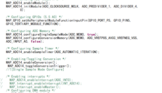
/* Initializing ADC (SMCLK/1/1) */
MAP_ADC14_enableModule();
MAP_ADC14_initModule(ADC_CLOCKSOURCE_SMCLK, ADC_PREDIVIDER_1, ADC_DIVIDER_1,
0);
/*
* Debug
* Configuring P1.0 as output
*/
MAP_GPIO_setAsOutputPin(GPIO_PORT_P1, GPIO_PIN0);
P1OUT &= ~BIT0;
/*
* Configuring GPIOs (5.5 A0)
*/
MAP_GPIO_setAsPeripheralModuleFunctionInputPin(GPIO_PORT_P5, GPIO_PIN5,
GPIO_TERTIARY_MODULE_FUNCTION);
/*
* Debug: set TA0.1 as output to see ADC trigger signal
*/
MAP_GPIO_setAsPeripheralModuleFunctionOutputPin(GPIO_PORT_P2, GPIO_PIN4,
GPIO_PRIMARY_MODULE_FUNCTION);
/*
* Configuring P1.1 as an input and enabling interrupt, the timer is started from
* GPIO ISR.
*/
MAP_GPIO_setAsInputPinWithPullUpResistor(GPIO_PORT_P1, GPIO_PIN1);
MAP_GPIO_interruptEdgeSelect(GPIO_PORT_P1,GPIO_PIN1,GPIO_HIGH_TO_LOW_TRANSITION);
MAP_GPIO_clearInterruptFlag(GPIO_PORT_P1, GPIO_PIN1);
MAP_GPIO_enableInterrupt(GPIO_PORT_P1, GPIO_PIN1);
MAP_Interrupt_enableInterrupt(INT_PORT1);
/*
* Configuring ADC Memory, repeat-single-channel, A0
*/
MAP_ADC14_configureSingleSampleMode(ADC_MEM0, true);
/*
* Configuring ADC Memory, reference, and single ended conversion
* A0 goes to mem0, AVcc is the reference, and the conversion is
* single-ended
*/
MAP_ADC14_configureConversionMemory(ADC_MEM0, ADC_VREFPOS_AVCC_VREFNEG_VSS,
ADC_INPUT_A0, false);
/*
* Configuring the sample trigger to be sourced from Timer_A0 CCR1 and on the
* rising edge, default samplemode is extended (SHP=0)
*/
MAP_ADC14_setSampleHoldTrigger(ADC_TRIGGER_SOURCE1, false);
/* Enabling the interrupt when a conversion on channel 1 is complete and
* enabling conversions */
MAP_ADC14_enableInterrupt(ADC_INT0);
MAP_ADC14_enableConversion();
/* Enabling Interrupts */
MAP_Interrupt_enableInterrupt(INT_ADC14);
MAP_Interrupt_enableMaster();
/* Going to sleep */
MAP_PCM_gotoLPM0();
while(1);
}
/* This interrupt is fired whenever a conversion is completed and placed in
* ADC_MEM0 */
void ADC14_IRQHandler(void)
{
uint64_t status;
status = MAP_ADC14_getEnabledInterruptStatus();
MAP_ADC14_clearInterruptFlag(status);
if (status & ADC_INT0)
{
resultsBuffer[resPos++] = MAP_ADC14_getResult(ADC_MEM0);
if(resPos == 0)
{
P1OUT |= BIT0;
MAP_Timer_A_stopTimer(TIMER_A0_BASE);
MAP_Timer_A_clearTimer(TIMER_A0_BASE);
P1OUT &= ~BIT0;
}
}
}
void PORT1_IRQHandler(void)
{
if(P1->IV == 4)
{
P1OUT |= BIT0;
while(P1->IFG & BIT1)
{
P1->IFG &= ~BIT1;
}
MAP_Timer_A_generatePWM(TIMER_A0_BASE, &timerA_PWM);
P1OUT &= ~BIT0;
}
}
void DMA_INT1_IRQHandler(void)
{
__no_operation();
}
/*
* -------------------------------------------
* MSP432 DriverLib - v3_10_00_09
* -------------------------------------------
*
* --COPYRIGHT--,BSD,BSD
* Copyright (c) 2014, Texas Instruments Incorporated
* All rights reserved.
*
* Redistribution and use in source and binary forms, with or without
* modification, are permitted provided that the following conditions
* are met:
*
* * Redistributions of source code must retain the above copyright
* notice, this list of conditions and the following disclaimer.
*
* * Redistributions in binary form must reproduce the above copyright
* notice, this list of conditions and the following disclaimer in the
* documentation and/or other materials provided with the distribution.
*
* * Neither the name of Texas Instruments Incorporated nor the names of
* its contributors may be used to endorse or promote products derived
* from this software without specific prior written permission.
*
* THIS SOFTWARE IS PROVIDED BY THE COPYRIGHT HOLDERS AND CONTRIBUTORS "AS IS"
* AND ANY EXPRESS OR IMPLIED WARRANTIES, INCLUDING, BUT NOT LIMITED TO,
* THE IMPLIED WARRANTIES OF MERCHANTABILITY AND FITNESS FOR A PARTICULAR
* PURPOSE ARE DISCLAIMED. IN NO EVENT SHALL THE COPYRIGHT OWNER OR
* CONTRIBUTORS BE LIABLE FOR ANY DIRECT, INDIRECT, INCIDENTAL, SPECIAL,
* EXEMPLARY, OR CONSEQUENTIAL DAMAGES (INCLUDING, BUT NOT LIMITED TO,
* PROCUREMENT OF SUBSTITUTE GOODS OR SERVICES; LOSS OF USE, DATA, OR PROFITS;
* OR BUSINESS INTERRUPTION) HOWEVER CAUSED AND ON ANY THEORY OF LIABILITY,
* WHETHER IN CONTRACT, STRICT LIABILITY, OR TORT (INCLUDING NEGLIGENCE OR
* OTHERWISE) ARISING IN ANY WAY OUT OF THE USE OF THIS SOFTWARE,
* EVEN IF ADVISED OF THE POSSIBILITY OF SUCH DAMAGE.
* --/COPYRIGHT--*/
/*******************************************************************************
* MSP432 ADC14 - Single Channel Continuous Sample w/ Timer_A Trigger
*
* Description: In this ADC14 code example, a single input channel is sampled
* using the standard 3.3v reference. The source of the sample trigger for this
* example is Timer_A CCR1. The ADC is setup to continuously sample/convert
* from A0 when the trigger starts and store the results in resultsBuffer (it
* is setup to be a circular buffer where resPos overflows to 0). Timer_A, CCR0
* and CCR1 are configured to generate a PWM. The CCR0 value is 23 and CCR1 is
* set to 11, resulting in a PWM of 1us period. The sample time is driven by
* the ADC clock and not the PWM duty cycle.
*
* The PWM is started once the GPIO interrupt for P1.1 is serviced.
*
* MSP432P401
* ------------------
* /|\| |
* | | |
* --|RST P5.5 |<--- A0 (Analog Input)
* | |
* | P1.1 |<--- GPIO trigger to Start conversions
* | |
* | P1.0 |---> Debug port to show DMA ISR
* | P2.4 |---> Debug TA0.1, ADC trigger
* | |
*
* Author: Timothy Logan/ C. Sterzik
******************************************************************************/
/* DriverLib Includes */
#include "driverlib.h"
/* Standard Includes */
#include <stdint.h>
#include <stdbool.h>
#define ARRAY_LENGTH 256
/*
* Timer_A Compare Configuration Parameter
* CCR1 is used to trigger the ADC14, conversion time
* is defined by the resolution
* 14bit -> 16 cycles + 1 cycle (SLAU356d, 20.2.8.3)
* 12bit -> 14 cycles + 1 cycle
* 10bit -> 11 cycles + 1 cycle
* 8bit -> 9 cycles + 1 cycle
*
* In this example, 14-bit resolution at 24Mhz ~708ns conversion time
* Sample time is defined by 4 ADC clocks
* Sample period is 24/24Mhz = 1us
*/
const Timer_A_PWMConfig timerA_PWM =
{
.clockSource = TIMER_A_CLOCKSOURCE_SMCLK,
.clockSourceDivider = TIMER_A_CLOCKSOURCE_DIVIDER_1,
.timerPeriod = 23,
.compareRegister = TIMER_A_CAPTURECOMPARE_REGISTER_1,
.compareOutputMode TIMER_A_OUTPUTMODE_SET_RESET,
.dutyCycle = 11
};
/* DMA Control Table */
#if defined(__TI_COMPILER_VERSION__)
#pragma DATA_ALIGN(MSP_EXP432P401RLP_DMAControlTable, 1024)
#elif defined(__IAR_SYSTEMS_ICC__)
#pragma data_alignment=1024
#elif defined(__GNUC__)
__attribute__ ((aligned (1024)))
#elif defined(__CC_ARM)
__align(1024)
#endif
static DMA_ControlTable MSP_EXP432P401RLP_DMAControlTable[16];
/* Statics */
static volatile uint16_t resultsBufferPrimary[ARRAY_LENGTH];
static volatile uint16_t resultsBufferAlternate[ARRAY_LENGTH];
int main(void)
{
/* Halting WDT */
MAP_WDT_A_holdTimer();
MAP_Interrupt_enableSleepOnIsrExit();
/* Starting HFXT in non-bypass mode without a timeout. Before we start
* we have to change VCORE to 1 to support the 48MHz frequency */
MAP_PCM_setCoreVoltageLevel(PCM_VCORE1);
MAP_FlashCtl_setWaitState(FLASH_BANK0, 1);
MAP_FlashCtl_setWaitState(FLASH_BANK1, 1);
/*
* Setting up clocks
* MCLK = MCLK = 48MHz
* SMCLK = MCLK/2 = 24Mhz
* ACLK = REFO = 32Khz
*/
MAP_CS_setDCOFrequency(48000000);
MAP_CS_initClockSignal(CS_ACLK, CS_REFOCLK_SELECT, CS_CLOCK_DIVIDER_1);
MAP_CS_initClockSignal(CS_SMCLK, CS_DCOCLK_SELECT, CS_CLOCK_DIVIDER_2);
MAP_CS_initClockSignal(CS_MCLK, CS_DCOCLK_SELECT, CS_CLOCK_DIVIDER_1);
/* Initializing ADC (SMCLK/1/1) */
MAP_ADC14_enableModule();
MAP_ADC14_initModule(ADC_CLOCKSOURCE_SMCLK, ADC_PREDIVIDER_1, ADC_DIVIDER_1,
0);
/*
* Debug
* Configuring P1.0 as output
*/
MAP_GPIO_setAsOutputPin(GPIO_PORT_P1, GPIO_PIN0);
P1OUT &= ~BIT0;
/*
* Configuring GPIOs (5.5 A0)
*/
MAP_GPIO_setAsPeripheralModuleFunctionInputPin(GPIO_PORT_P5, GPIO_PIN5,
GPIO_TERTIARY_MODULE_FUNCTION);
/*
* Debug: set TA0.1 as output to see ADC trigger signal
*/
MAP_GPIO_setAsPeripheralModuleFunctionOutputPin(GPIO_PORT_P2, GPIO_PIN4,
GPIO_PRIMARY_MODULE_FUNCTION);
/*
* Configuring P1.1 as an input and enabling interrupt, the timer is started from
* GPIO ISR.
*/
MAP_GPIO_setAsInputPinWithPullUpResistor(GPIO_PORT_P1, GPIO_PIN1);
MAP_GPIO_interruptEdgeSelect(GPIO_PORT_P1,GPIO_PIN1,GPIO_HIGH_TO_LOW_TRANSITION);
MAP_GPIO_clearInterruptFlag(GPIO_PORT_P1, GPIO_PIN1);
MAP_GPIO_enableInterrupt(GPIO_PORT_P1, GPIO_PIN1);
/*
* Configuring ADC Memory, repeat-single-channel, A0
*/
MAP_ADC14_configureSingleSampleMode(ADC_MEM0, true);
/*
* Configuring ADC Memory, reference, and single ended conversion
* A0 goes to mem0, AVcc is the reference, and the conversion is
* single-ended
*/
MAP_ADC14_configureConversionMemory(ADC_MEM0, ADC_VREFPOS_AVCC_VREFNEG_VSS,
ADC_INPUT_A0, false);
/*
* Configuring the sample trigger to be sourced from Timer_A0 CCR1 and on the
* rising edge, default samplemode is extended (SHP=0)
*/
MAP_ADC14_setSampleHoldTrigger(ADC_TRIGGER_SOURCE1, false);
/* Enabling the interrupt when a conversion on channel 1 is complete and
* enabling conversions */
MAP_ADC14_enableInterrupt(ADC_INT0);
MAP_ADC14_enableConversion();
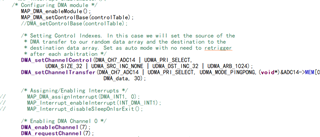
/* Configuring DMA module */
MAP_DMA_enableModule();
MAP_DMA_setControlBase(MSP_EXP432P401RLP_DMAControlTable);
/*
* Setup the DMA + ADC14 interface
*/
MAP_DMA_disableChannelAttribute(DMA_CH7_ADC14,
UDMA_ATTR_ALTSELECT | UDMA_ATTR_USEBURST |
UDMA_ATTR_HIGH_PRIORITY |
UDMA_ATTR_REQMASK);
/*
* Setting Control Indexes. In this case we will set the source of the
* DMA transfer to ADC14 Memory 0 and the destination to the destination
* data array.
*/
MAP_DMA_setChannelControl(UDMA_PRI_SELECT | DMA_CH7_ADC14,
UDMA_SIZE_16 | UDMA_SRC_INC_NONE | UDMA_DST_INC_16 | UDMA_ARB_1);
MAP_DMA_setChannelTransfer(UDMA_PRI_SELECT | DMA_CH7_ADC14,
UDMA_MODE_PINGPONG, (void*) &ADC14->MEM[0],
(void*)resultsBufferPrimary, ARRAY_LENGTH);
MAP_DMA_setChannelControl(UDMA_ALT_SELECT | DMA_CH7_ADC14,
UDMA_SIZE_16 | UDMA_SRC_INC_NONE | UDMA_DST_INC_16 | UDMA_ARB_1);
MAP_DMA_setChannelTransfer(UDMA_ALT_SELECT | DMA_CH7_ADC14,
UDMA_MODE_PINGPONG, (void*) &ADC14->MEM[0],
(void*)resultsBufferAlternate, ARRAY_LENGTH);
/* Assigning/Enabling Interrupts */
MAP_DMA_assignInterrupt(DMA_INT1, 7);
MAP_DMA_assignChannel(DMA_CH7_ADC14);
MAP_DMA_clearInterruptFlag(7);
/* Enabling Interrupts */
MAP_Interrupt_enableInterrupt(INT_DMA_INT1);
MAP_Interrupt_enableInterrupt(INT_PORT1);
MAP_Interrupt_enableMaster();
/* Going to sleep */
MAP_PCM_gotoLPM0();
__no_operation();
}
/* Completion interrupt for ADC14 MEM0 */
__attribute__((ramfunc)) // Requires compiler TI v15.12.1.LTS
void DMA_INT1_IRQHandler(void)
{
MAP_Timer_A_stopTimer(TIMER_A0_BASE);
MAP_DMA_disableChannel(7);
P1->OUT |= BIT0;
/*
* Switch between primary and alternate bufferes with DMA's PingPong mode
*/
if (MAP_DMA_getChannelAttribute(7) & UDMA_ATTR_ALTSELECT)
{
// MAP_DMA_setChannelControl(UDMA_PRI_SELECT | DMA_CH7_ADC14,
// UDMA_SIZE_16 | UDMA_SRC_INC_NONE | UDMA_DST_INC_16 | UDMA_ARB_1);
// MAP_DMA_setChannelTransfer(UDMA_PRI_SELECT | DMA_CH7_ADC14,
// UDMA_MODE_PINGPONG, (void*) &ADC14->MEM[0],
// resultsBufferPrimary, ARRAY_LENGTH);
MSP_EXP432P401RLP_DMAControlTable[7].control =
(MSP_EXP432P401RLP_DMAControlTable[7].control & 0xff000000 ) |
(((ARRAY_LENGTH)-1)<<4) | 0x03;
}
else
{
// MAP_DMA_setChannelControl(UDMA_ALT_SELECT | DMA_CH7_ADC14,
// UDMA_SIZE_16 | UDMA_SRC_INC_NONE | UDMA_DST_INC_16 | UDMA_ARB_1);
// MAP_DMA_setChannelTransfer(UDMA_ALT_SELECT | DMA_CH7_ADC14,
// UDMA_MODE_PINGPONG, (void*) &ADC14->MEM[0],
// resultsBufferAlternate, ARRAY_LENGTH);
MSP_EXP432P401RLP_DMAControlTable[15].control =
(MSP_EXP432P401RLP_DMAControlTable[15].control & 0xff000000 ) |
(((ARRAY_LENGTH)-1)<<4) | 0x03;
}
P1->OUT &= ~BIT0;
}
void PORT1_IRQHandler(void)
{
P1->OUT |= BIT0;
P1IFG &= ~BIT1;
MAP_DMA_enableChannel(7);
MAP_Timer_A_generatePWM(TIMER_A0_BASE, &timerA_PWM);
P1->OUT &= ~BIT0;
}有没有不需要DMA中断的,
您可以在下面路径找到
C:\ti\simplelink_msp432p4_sdk_3_40_01_02\examples\nortos\MSP_EXP432P401R\driverlib
如 adc14_multiple_channel_no_repeat
