我想配置一个PE4,PE5两通道采样,配置采样率500k是先使能在配置,还是其他?
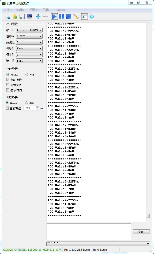
在获得数据的时候只有一个函数ADCSequenceDataGet();会不会两通道的数据获得重合?怎样才能精确的获得2通道数据?
void ADC0_init(void)
{
// Enable GPIO for ADC
SysCtlADCSpeedSet(SYSCTL_ADCSPEED_500KSPS);
SysCtlPeripheralEnable(SYSCTL_PERIPH_GPIOE);
SysCtlPeripheralEnable(SYSCTL_PERIPH_ADC0);
GPIOPinTypeADC(GPIO_PORTE_BASE, GPIO_PIN_4);// Enable pin PE4_AIN9
GPIOPinTypeADC(GPIO_PORTE_BASE, GPIO_PIN_5);// Enable pinPE5 _AIN8
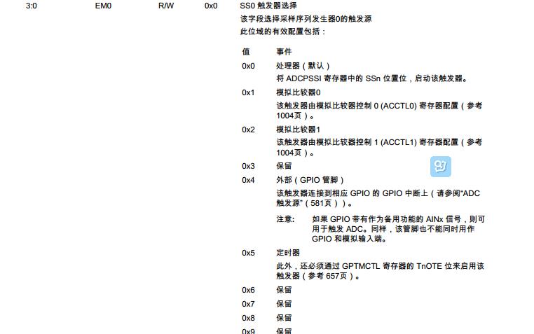
ADCSequenceConfigure(ADC0_BASE, 1, ADC_TRIGGER_PROCESSOR, 0);
ADCSequenceStepConfigure(ADC0_BASE, 1, 0, ADC_CTL_CH8|ADC_CTL_CH9| ADC_CTL_IE |ADC_CTL_END);
ADCSequenceEnable(ADC0_BASE, 1);
ADCIntClear(ADC0_BASE, 1);//
// ADCIntRegister(ADC0_BASE,1,ADC0IntHandler);//
ADCIntEnable(ADC0_BASE,1);//
}