SM470低功耗standby模式唤醒问题:
1、设置SM470进入standby模式,通过RTI中断进行唤醒。唤醒后程序从哪里开始运行?按理说standby模式是掉电,唤醒相当于复位吗?
2、目前检测到,退出低功耗模式后,程序只能在RTI中断中运行,并未重新从main()开始执行,RTI中断中需要做什么操作,才能让程序再次运行吗?
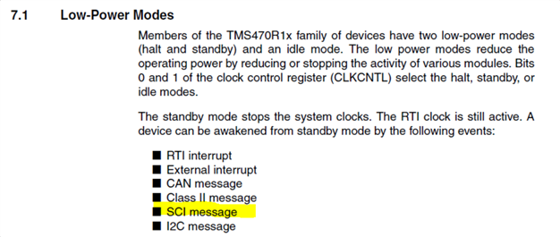
3、手册说,standby模式可以通过SCI信息唤醒,具体如何唤醒?是SCI中断还是只要接收缓冲器收到数据就能唤醒?
This thread has been locked.
If you have a related question, please click the "Ask a related question" button in the top right corner. The newly created question will be automatically linked to this question.
SM470低功耗standby模式唤醒问题:
1、设置SM470进入standby模式,通过RTI中断进行唤醒。唤醒后程序从哪里开始运行?按理说standby模式是掉电,唤醒相当于复位吗?
2、目前检测到,退出低功耗模式后,程序只能在RTI中断中运行,并未重新从main()开始执行,RTI中断中需要做什么操作,才能让程序再次运行吗?
3、手册说,standby模式可以通过SCI信息唤醒,具体如何唤醒?是SCI中断还是只要接收缓冲器收到数据就能唤醒?
你好,工程师对这个芯片没有太多的经验和知识,这是一个比较老的芯片。
1、设置SM470进入standby模式,通过RTI中断进行唤醒。唤醒后程序从哪里开始运行?按理说standby模式是掉电,唤醒相当于复位吗?
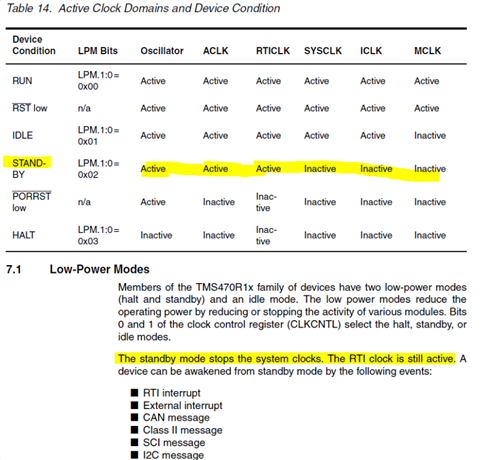
我认为唤醒后,应该从进入待机模式的指令重新启动。唤醒不应导致设备重置。如果你看下面的 LPM 描述,OSC、ACLK 和 RTICLK 仍然是振荡器。RTI 模块仍在运行。

2、目前检测到,退出低功耗模式后,程序只能在RTI中断中运行,并未重新从main()开始执行,RTI中断中需要做什么操作,才能让程序再次运行吗?
如果您已经确认唤醒后,处理器正在执行 RTI 中断,那么我相信唤醒正在工作。一旦退出中断ISR,它应该恢复正常操作,对吧?当然,在退出 ISR 之前您需要清除所有中断标志。
3、手册说,standby模式可以通过SCI信息唤醒,具体如何唤醒?是SCI中断还是只要接收缓冲器收到数据就能唤醒?
根据TMS470系统模块用户指南,SCI可用于唤醒时钟。我认为它的工作原理是,RX 引脚上的高电平到低电平将导致时钟控制器发生唤醒事件,以唤醒所有时钟。

我需要用RTI来延迟比如几个小时
参考下下面的回复:
You need to enable the 11-bit preload that will create a 32-bit RTI counter. Refer to the below description.
The RTI is clocked by the RTICLK, which runs at SYSCLK frequency (see
Section 7, Clocks, on page 43). The RTI counts RTICLK periods based upon
the state of the CPU and the control bits CNTEN.1:0 (RTICNTEN.1:0). An
11-bit preload value, PRELD.10:0 (RTIPCTL.10:0), provides the prescale
value. The prescale, MOD.10:0 (RTICNTR.10:0) counts down from the
preload to 0.
When the prescale counts down to 0, a 21-bit counter is incremented. The
counter, CNTR.20:0 (RTICNTR.31:11), is a count up counter. During a read
access, both of the RTI counters (MOD.10:0 and CNTR.20:0) are read
together in the same cycle as a single 32-bit value (RTICNTR.31:0). However,
because the modulo M counter (MOD.10:0) is a down counter, a calculation
needs to be performed to convert the 32-bit RTI counter value into system
clock cycles which is given by Equation 1:
(EQ 1)
Where:
M = Preload value PRELD.10:0 (RTIPCL.10:0),
when PRELD.10:0 = 0, M = 2048
m = Current value of MOD.10:0 (RTICNTR.10:0)
N = Current value of CNTR.20:0 (RTICNTR.31:11)
The real-time counter can generate three distinct interrupts off of this up
counter:
❏ Tap interrupt
❏ Two compare interrupts (Compare1 and Compare 2)