Part Number: SM470R1B1M-HT
SM470低功耗standby模式唤醒问题:
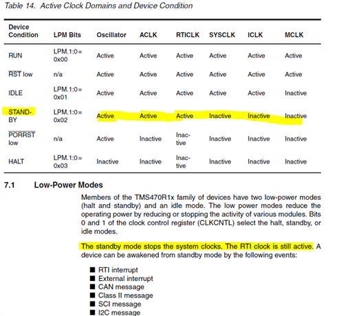
1、设置SM470进入standby模式,通过RTI中断进行唤醒。唤醒后程序从哪里开始运行?按理说standby模式是掉电,唤醒相当于复位吗?
2、目前检测到,退出低功耗模式后,程序只能在RTI中断中运行,并未重新从main()开始执行,RTI中断中需要做什么操作,才能让程序再次运行吗?
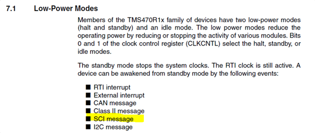
3、手册说,standby模式可以通过SCI信息唤醒,具体如何唤醒?是SCI中断还是只要接收缓冲器收到数据就能唤醒?