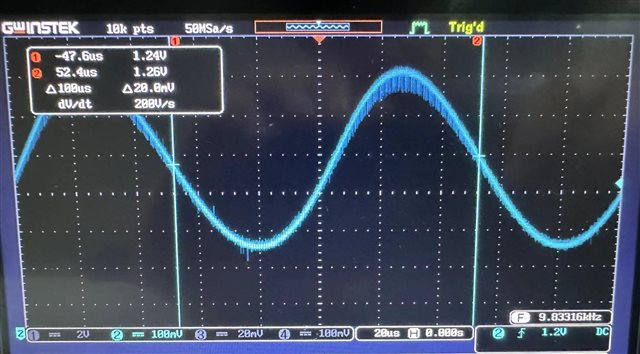
您好,我在使用此款参考设计时,为了使其更适用于我的旋转变压器参数,我尝试将激磁频率从5kHz修改至10kHz(具体操作是将EXC_STEPS_PER_PERIOD 64 /* 2^6 -> 6-bit resolution per EXC period */这一行函数中的64修改到32),但是测试端子显示的OEXC激磁波形出现了稍微的失真(图形有点偏移),请问是否是我的操作有误,还是别的原因?希望工程师的尽快回复,特别感谢!

This thread has been locked.
If you have a related question, please click the "Ask a related question" button in the top right corner. The newly created question will be automatically linked to this question.
您好,我在使用此款参考设计时,为了使其更适用于我的旋转变压器参数,我尝试将激磁频率从5kHz修改至10kHz(具体操作是将EXC_STEPS_PER_PERIOD 64 /* 2^6 -> 6-bit resolution per EXC period */这一行函数中的64修改到32),但是测试端子显示的OEXC激磁波形出现了稍微的失真(图形有点偏移),请问是否是我的操作有误,还是别的原因?希望工程师的尽快回复,特别感谢!

你好,参考下工程师的回复:
I believe you need to play with the cut-off frequency of the MFB filter. Please take a snapshot from of the EXC+ and EXC- signals with the reference to ground. Use the in-built function in the oscilloscope to do the delta (Math Ch1-Ch2). It provides clearer picture.
For the filter cut-off frequency change, use http://sim.okawa-denshi.jp/en/OPtazyuLowkeisan.htm . This online tool helps you to quickly evaluate new values of C3 and C4. Set the frequency to ~20 kHz.