This thread has been locked.

If you have a related question, please click the "Ask a related question" button in the top right corner. The newly created question will be automatically linked to this question.

BOOSTXL-DRV3245AQ1: DRV3245AQ1

Part Number: BOOSTXL-DRV3245AQ1


Hi,

Due to the inability to contact your company's after-sales engineer, we can only post a request for help here.

We found a phenomenon when using DRV3245 and need your company to confirm whether it belongs to the chip characteristics.
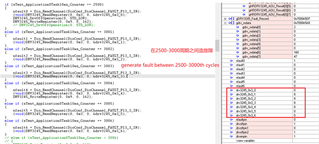
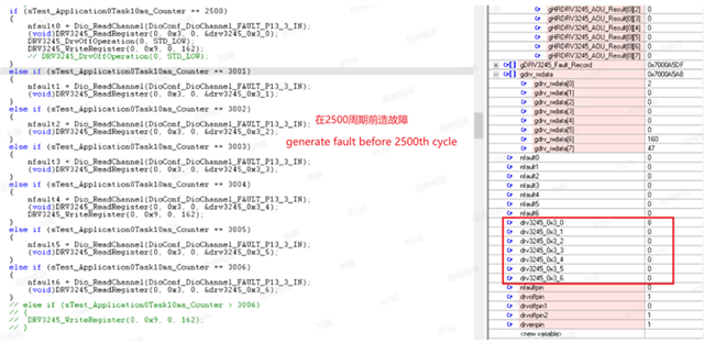
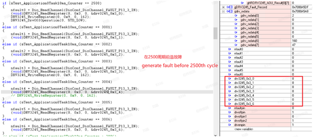
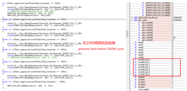
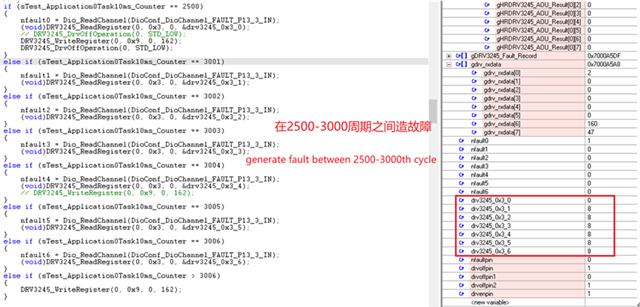
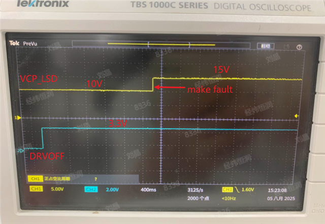
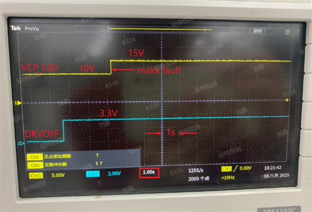
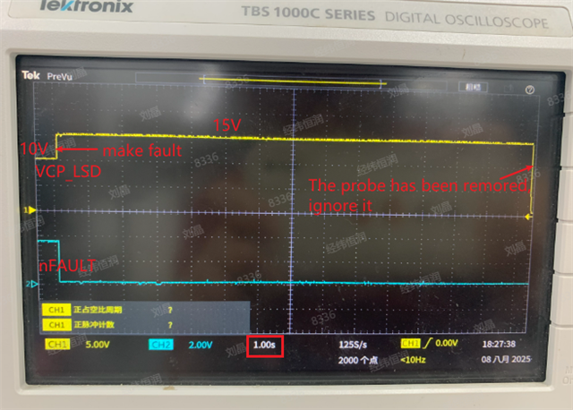
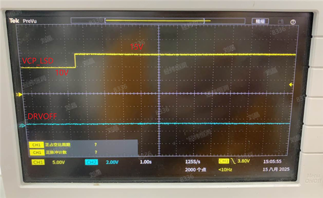
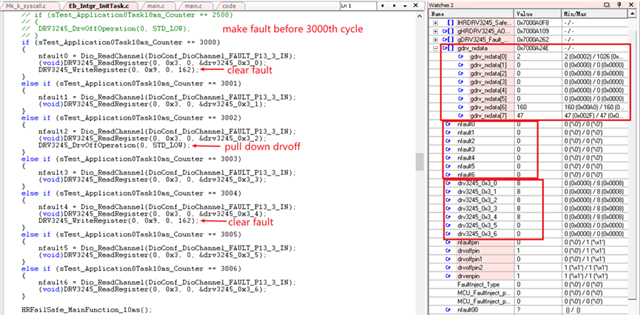
After pulling down the DRVOFF pin of DRV3245, a VLSD overvoltage fault is generated, and the fault condition persists. At this time:
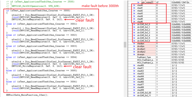
1. After the fault occurs, both the register and nFAULT can report the fault, regardless of whether DRVOFF is pulled down or which fault condition occurs first.
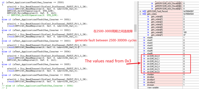
2. After clearing the fault once, nFAULT can report a fault, but the register cannot reset the flag position again.

  • 您好,

    已经收到了您的案例,调查需要些时间,感谢您的耐心等待。

  • Please highlight in the datasheet which faults you are reading, I do not see VLSD in the datasheet.

  • This is the fault, VCP_LSD_OVLO

  • Could you share the SPI read back from the device so we can see which faults are occurring and some waveforms showing the VCP_LSD voltage and DRVOFF signals.

  • Note 1: The drvoff pull-down in the following code refers to the drvoff pull-up near the 3245 end.
    Note 2: The low side charge pump overvoltage fault has been objectively present.

    1. DRVOFF pull-down → Fault generation → Clear the fault once in the 3004th cycle: No fault can be read after 3004th cycle

    2. Fault generation → drvoff pull-down → clear fault once: no fault can be read again after 2500th cycle

    3. Fault generation → clear fault once → drvoff pull-down → clear fault once in the 3003th cycle: no fault can be read again after 3003th cycle

    4. Fault generation → clear the fault once → drvoff pull-down → clear the fault after 3006th cycle: no fault can be read after 3006th cycle

    5. Drvoff pull-down → fault generation → clear the fault after 3006th cycle: no fault can be read after 3006th cycle

  • These two graphs are data that occurred at the same time. The upper graph shows the voltage changes of VCP_LSD and DRVOFF, while the lower graph shows the values read from the register 0x3. If you cannot understand the code of the second graph, please find someone who can understand it.

  • Unfortunately the code review is not pointing to a clear error or hypothesis.

    Can you share waveform of the DRVOFF, VCP_LSD, and GH/GL so that we can review?

  • Is the customer asking why they are seeing the VCP_LSD voltage is going from 10V to 15V? Or is the question why the VCP_LSD_OVLO bit is changing from 1 to 0 after a clear fault event even though the VCP_LSD overvoltage event is still present? Is the customer forcing the VCP_LSD pin to 15V externally?

    Additionally, for the variable sTest_Application0Task10ms_Counter, based on the name it seems that this variable is incremented by 1 after every 10ms, is that correct? So between cycles 2500 and 3000 are (3000-2500)*10ms = 5000ms?

  • Thank you very much for carefully reading my comment !

    The question is why the VCP_LSD_OVLO bit is changing from 1 to 0 after a clear fault event even though the VCP_LSD overvoltage event is still present.

    I did force the VCP_LSD pin to 15V through an external power supply, and it consistently displays 15V. The image in my previous comment can illustrate this.

    The variable sTest_Application0Task10ms_Counter is incremented by 1 after every 10ms.

  • Thanks for the clarification and confirmation! If DRVOFF is low and the test is repeated does the VCP_LSD_OVLO bit stay at 1 even after a clear fault event? 

    Since the variable is incremented by 1 after every 10ms, then there is 5 seconds between DRVOFF going high and the readback of the fault register and then shortly after that sending a clear fault command. Based on the waveform you provided, based on the scope division the time at which the clear fault is sent happens at a much later time compared to the time of the scope capture. With this in mind, I want to confirm that the overvoltage is still present when the clear fault is issued since the previous waveform doesn't show the state of the VCP_LSD pin voltage at the time of the clear fault command. One way to capture this is to have a GPIO on the MCU toggle when the clear faults command is sent, and then set the scope to trigger on that GPIO while probing nFAULT and VCP_LSD along with the GPIO.

    You mention that although the VCP_LSD_OVLO bit is cleared to 0 the nFAULT pin is still low. Could you read the rest of the status registers to see if there are any other faults being reported?

  • Thank you for your reply. As our oscilloscope only has two channels and cannot display the status of VCP_LSD, DRVOFF, and nFAULT simultaneously, I have tested it twice.
    As shown in the above figures, I have marked the time scale, with each square representing 1 second. I believe this time span can answer your question. The value read from the register is the same as my previous comment.

  • Thank you for your confirmation that the VCP_LSD OV condition is still present even after giving a clear fault command. Regarding my other questions: 

     If DRVOFF is low and the test is repeated does the VCP_LSD_OVLO bit stay at 1 even after a clear fault event? 

    You mention that although the VCP_LSD_OVLO bit is cleared to 0 the nFAULT pin is still low. Could you read the rest of the status registers to see if there are any other faults being reported?

  • 1. For your question one, I modified the code and conducted testing.

     If DRVOFF is low, the VCP_LSD_OVLO bit stay at 1 even after twice clear fault events.

    2. For your question two, I also modified the code and conducted testing.

    The two images represent the same testing process. I must clarify that the 'pull down DRVOFF' in the code refers to the pin near the MCU end, while the state near the DRV3245 end is the opposite. 

    I read the values of all state registers through an array--gdrv_rxdata[ ], and the debugger interface displayed the maximum and minimum values throughout the entire testing process. The results showed that only the maximum value of register 0x3 had changed, while the maximum values of other state registers were all 0. The maximum value of 0x1 was 1026, indicating that a fault had occurred before.

    In addition, I found an interesting phenomenon that DRVOFF seems to only affect faults related to gate output. I also caused AVDD_OVLO fault, and regardless of the DRVOFF status and whether the fault has been cleared, the AVDD-OVLO bit can always stay at 1.

    Thanks for your kind attention and look forward your prompt reply.