DRV3946-Q1: DEV3946 DRIVER SPI_ERR

Part Number: DRV3946-Q1

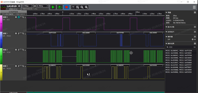
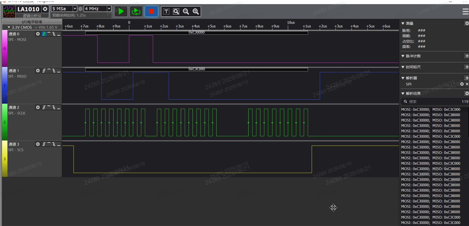
We have encountered the following issues during the development of the 3946 chip driver and seek assistance.First, we discovered that the SPI timing description in the DRV3946 datasheet was incorrect. Subsequently, we operated the SPI according to CPOL = 0 and CPHA = 0. However, during the initialization process, we found that the SPI_ERR bit occasionally set to 1 when reading the STATUS0 register, causing subsequent configuration initialization failures. The captured data from the logic analyzer is as follows. According to the datasheet description, the possible causes of SPI_ERR could be an incorrect number of CLK edges during the NCS low period or an invalid command CRC. The logic analyzer data confirms that the CLK edge count is correct, and reading STATUS0 does not require a CRC. Therefore, how should the SPI_ERR cause be analyzed? The data waveform is shown in the figure belowSecondly, we currently only have a demo of the evm_fw. Can you provide additional materials? Is the datasheet updated;Looking forward to your prompt reply. Thank you.
  • Thank you for your attention to TI products. We are verifying your issue, please wait for our reply.

  • Hello, is there a conclusion and response?

    1. Add Delays After Power-Up

      • Increase the delay between VDD stabilization and the first SPI transaction
      • Try 10ms, 50ms, or 100ms delays to rule out power-up timing
    2. Reduce SPI Clock Frequency

      • Temporarily reduce from 4 MHz to 1 MHz or lower during initialization
      • If the error disappears, it confirms a timing margin issue
    3. Scope the Power Supply

      • Monitor VDD and PVDD during initialization with an oscilloscope
      • Look for voltage dips, ripple, or slow rise times
    4. Check Signal Integrity

      • Use an oscilloscope (not just logic analyzer) to examine:
        • Rise/fall times of all SPI signals
        • Overshoot/undershoot/ringing
        • Signal levels at the device pins (not just at the controller)
  • Hello, thank you for your support. After modifying the MCAL SPI transmission to be a one-time 24-bit transmission, the spi_err disappeared, but we encountered a new issue. During the initialization process, is there any additional requirement before clearing the fault register CMD1? When we sent the fault-clear command, the readback value was 0xffff. Additionally, is there an update to the datasheet? The CRC algorithm in the EVM demo does not match the description in the datasheet. The EVM demo uses a polynomial of 0x2f, while the datasheet specifies 0x97. Below is the screenshot of the data using 0x2f,looking forward your reply soon.

    ...

  • Hello, thank you for your support. After modifying the MCAL SPI transmission to be a one-time 24-bit transmission, the spi_err disappeared, but we encountered a new issue. During the initialization process, is there any additional requirement before clearing the fault register CMD1? When we sent the fault-clear command, the readback value was 0xffff. Additionally, is there an update to the datasheet? The CRC algorithm in the EVM demo does not match the description in the datasheet. The EVM demo uses a polynomial of 0x2f, while the datasheet specifies 0x97. Below is the screenshot of the data using 0x2f,looking forward your reply soon.