

We know that push-pull circuits come in many types, such as class A or class B amplifiers. Class B amplifiers are the ones used in practical applications. They are more efficient than class A, but they are often affected by crossover distortion.
So how does it affect it? How can it be reduced?
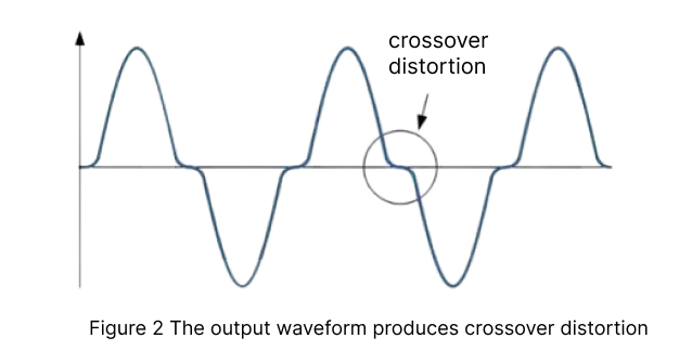
When the signal is distorted at 0V, the transistor will provide a voltage of 0.7v at the base-emitter junction before turning on. When the AC input voltage is applied to the push-pull amplifier, it increases from 0 until it reaches 0.7V, and the transistor remains off without any output.
So why does crossover distortion occur when VIN reaches zero? (Class B amplifier)
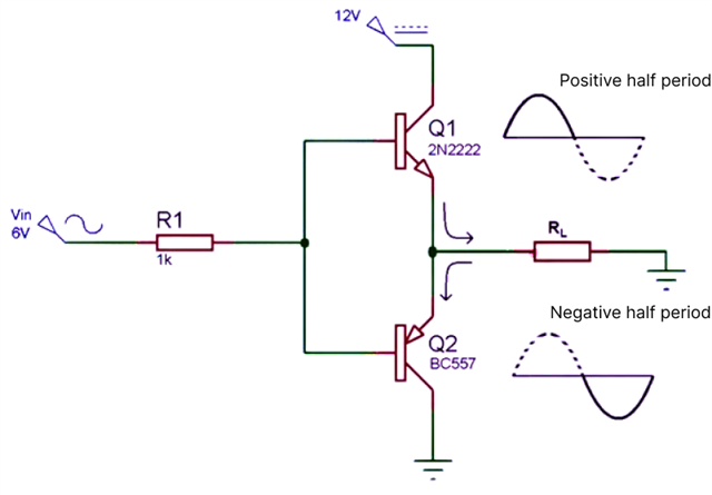
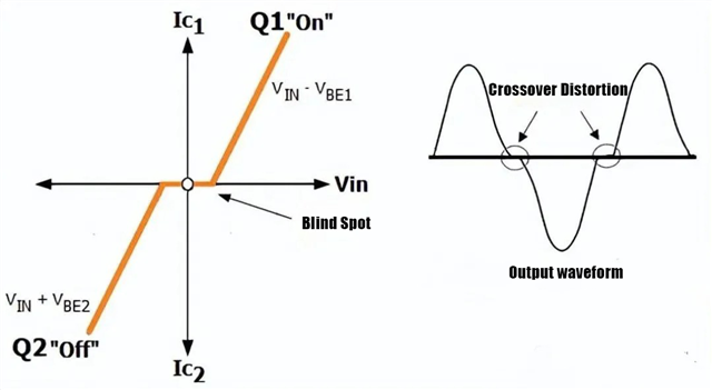
In fact, transistors Q1 and Q2 cannot be turned on at the same time. If Q1 is turned on, VIN must be greater than Vout, and if Q2 is turned on, Vin must be less than Vout. If VIN is equal to zero, Vout must also be equal to zero.
When VIN increases from zero, the output voltage Vout will also remain at zero. Until V IN is less than 0.7V, the output voltage shows a dead zone, and the same situation will occur when V IN starts to decrease from zero.
How to reduce the crossover distortion of the push-pull transistor circuit?
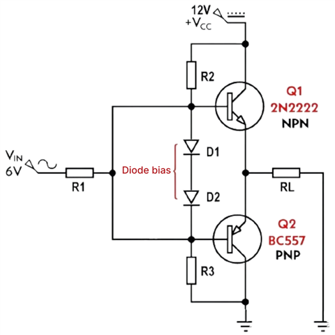
It can be corrected by using two diodes that are turned on at the transistor position, that is, the class AB amplifier circuit.
It uses the characteristics of both. From 0V to 0.7V, the diode is biased in the on state to make up for the 0.7 V loss of the emitter follower. At this time, the transistor has no signal at the base, which solves the crossover distortion problem.
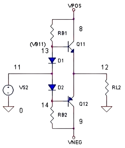
In addition, it can also be achieved by reducing the resistance value.
This is because the resistor RB1 controls the current of D1. The smaller RB1 is, the greater the current is, that is, the greater the voltage of the diode is, so when there is no input signal, the Vbe will be greater. This increased deviation will further reduce the distortion.
However, the specific application situation is still based on the actual circuit design.
