Part Number: ULC1001-DRV290XEVM
Other Parts Discussed in Thread: DRV2901
HI,
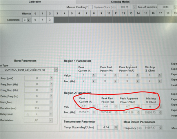
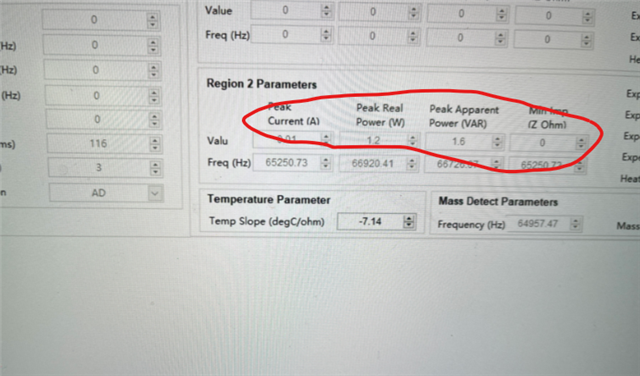
I used the ULC1001-DRV2901 EVM board to connect the LCS, and then ran the calibration on the GUI. In the water removal mode, the LCS water removal effect was obvious. I used a homemade PCB to connect the LCS, and ran the calibration. In the water removal mode, the LCS water removal effect was not obvious. However, the circuit of the ULC-DRV2901 is the same. I found that using the same LCS, the four measured values after calibration are different on the GUI. The first one is the EVM board, and the second one is the display of the PCB board on the GUI,I am confused as to why the values displayed in GUI Region2 are different when using the same LCS, and the values in Region2 cannot be manipulated.
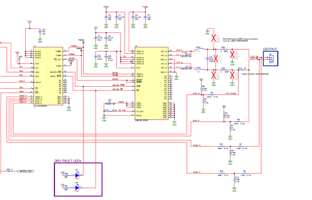
I used an oscilloscope to test the waveform voltage of the dehydration mode of the output port, and found that the waveform voltage of the EVM board is about 70V, while the output voltage of the board I laid out is only 37V, which results in a very unclear dehydration effect and insufficient power. I want to know how to make the output voltage of my layout board the same as the voltage of the EVM board, or which module in the circuit controls the output voltage and power. I don't know how to increase the output voltage and power of the DRV2901 on my layout board.
The drive circuit on my layout board is exactly the same as that on the EVM board.