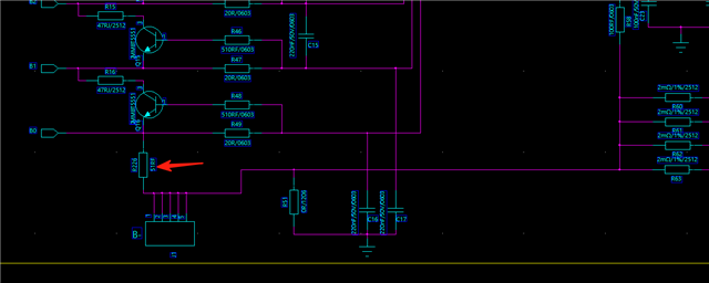
Hello, during the testing of charging and discharging, I found that the current sampling of VC1 was inaccurate. I suspect that the B-power line is too long, and VC0 and B - are connected together on the PCB. During charging and discharging, current flows through VC0 and B - on the PCB, causing deviation in the VCO. Currently, I have added a resistor between VC0 and B - on the PCB to solve this problem. I would like to inquire if this can be done.Or B - and VCO can be short circuited on the battery cell, not on the PCB.