Part Number: BQ79758-Q1
TI Expert:
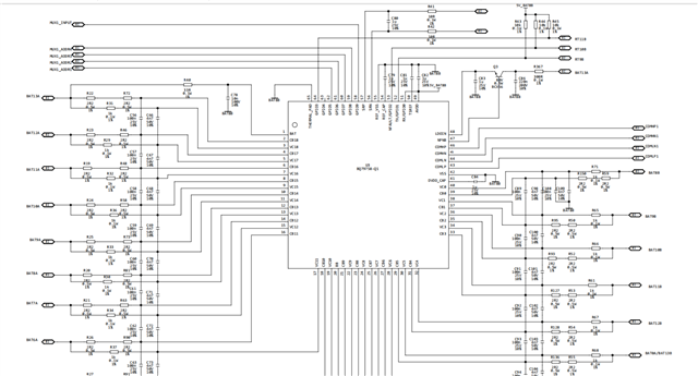
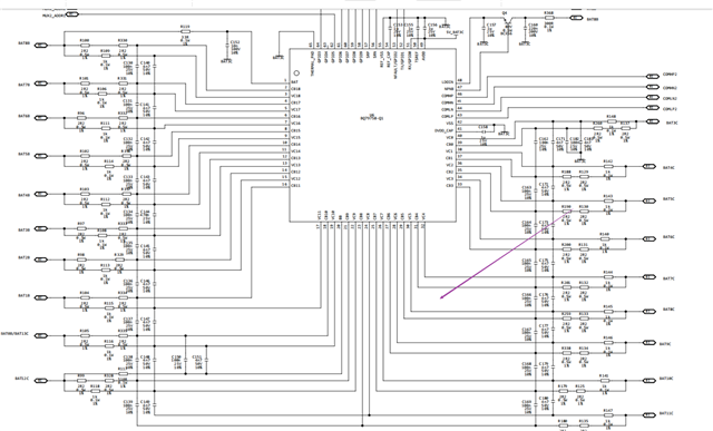
I encountered related issues in the BMS project. The entire system uses three BQ79758 chips to manage 52 battery cells. However, when collecting voltage, it was found that the battery voltage collected by the 18th channel of the first BQ chip was incorrect, with a deviation of nearly 100 mV (the actual voltage is 1.62V). Measuring the voltage between VC18 and VC17 with a multimeter also showed 1.62V. At the same time, the voltage collected by the fifth channel of the second chip also had a deviation of about 300 mV. Measuring the voltage between VC4 and VC5 with a multimeter showed that the actual battery voltage was 2.32V. May I ask what could cause this deviation in the collected voltage values when the voltage at the VC port is consistent with the actual battery voltage? Apart from these two channels having incorrect voltage readings, the battery voltage sampling of the other channels is normal, with deviations basically within 1-2 mV. Another question is, regarding the BQ79758 chip in actual use, if the requirement for voltage sampling accuracy is within 5 mV, is calibration necessary? Are the registers related to CAL_ADC mentioned in the chip manual used for calibration?
Here are some of my operations: