

Other Parts Discussed in Thread: LM61460
Hello Expert
Please support to check below design and give your comments.
Input voltage range: 9-16V
Output voltage range:2-8V, current configure:5V
Output current: max. 5A
fsw=400KHz
Output voltage ripple: 3%
load transient range: 5A to 0.5A
Transient response voltage change: 5%
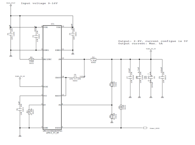
Q1: consider the cost saving, i choose one Electrolytic capacitor 100uF, esr=35mR, ripple current=1.7A, with 1*10uF and 1*4.7uF, can you check it's OK or not->especially for 100uF EC?
Q2: choose one 10uF with 2*220nF at input pin, it's OK or not?
Q3: Customer want to adjust the output voltage, do you have good solution for current BUCK LM61460?
