This thread has been locked.

If you have a related question, please click the "Ask a related question" button in the top right corner. The newly created question will be automatically linked to this question.

PMP41009: PMP41009: UCC28740-Q1

Other Parts Discussed in Thread: PMP41009, UCC28740-Q1, UCC28740, UCC28742

Hi,May I ask if I can replace the UCC28740-Q1 chip in the PMP41009 design circuit with a chip from the UCCx8C5x series? If not, what is the reason? Can chips from the UCCx8C5x series be used in a dual-switch cascaded flyback circuit like the one designed in PMP41009? Thank you for your previous reply. I really appreciate it.

  • Hi,

    Yes you can change out the IC, the most popular one we have is the UCC28730-Q1. The reason this is preferred is because it is a primary-side regulator which avoids the need for the optocoupler.

    When changing from a dedicated flyback controller like to UCC28740 to the UCCx8C5x series, you are changing from a Valley switching controller that uses AM/FM control law to maximize the efficiency over the entire load range. The UCCx8C5x is a general purpose PWM which runs at a fixed frequency and will be less efficient. 

    I hope this answers your question. 

  • Hi, do you have any good chip recommendations? The maximum operating frequency should preferably be at least 130KHz, and the efficiency should be higher than that of the UCCx8C5x series chips. Thank you.

  • Hi,

    What how much output power do you need to support and do you need AEC-Q100 qualified devices?

  • Hello, the output power is 40W, and it does not need to comply with the AEC-Q100 standard. I want to build a high-voltage, wide-range input flyback switching power supply with a dual-switch cascaded structure like PMP41009. Do you have any good chip recommendations? The maximum operating frequency should preferably be at least 130KHz, and the efficiency should be higher than that of the UCCx8C5x series chips. Thank you.

  • Hello, I have another question to ask you. In the circuit design like PMP41009, the control chip only needs to control one MOSFET. Do I need to add a driver chip between the control chip and the SiC MOSFET? If so, do you have any recommended driver chips? Thank you, and wish you all the best in life.

  • Hi,

    The UCC28742 has a maximum frequency of 130kHz. The UCC28740 is limited to around 100kHz. Because this is a valley switching controller, it will be more efficient than the UCCx8C5x series. 

    As for the gate driver, we have numerous non-isolated gate drivers that can do the job. It depends on the actual SiC as some may require a negative voltage to ensure turn-off. One possibility for a gate driver could be the UCC51702

    I hope this answers your question.

  • 您好,我刚刚查看了该UCC28742的规格表,发现它的最大工作频率列为 80KHz,与您提到的 130KHz 不符。此外,我选择的SiC MOSFET需要20V的导通电压和-5V的导通电压,而UCC51702的数据似乎表明它无法满足这些要求。您能验证一下并告诉我这两款芯片是否可以使用吗?谢谢。

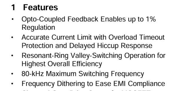
  • 您好,下图是我在查看 UCC28742 数据表时发现的。我有点困惑关于其最大工作频率的哪些信息是正确的。你能告诉我吗?此外,我选择的SiC MOSFET需要20V的导通电压和-5V的导通电压。您能告诉一下哪种驱动芯片(UCC51702 或 UCC5350M)更适合我的电路设计吗?我期待您的回复。谢谢。

  • Hi,

    The maximum frequency is 130Khz:

    This converter uses AM/FM control law to maximize the efficiency over the entire load. So the frequency does vary as a function of the load. 

    If you need a gate driver with a negative 5V rail, the customer would first have to create a negative bias rail and then select the proper gate driver. For this you can start a thread with the gate driver team. 

    I hope this helps. 

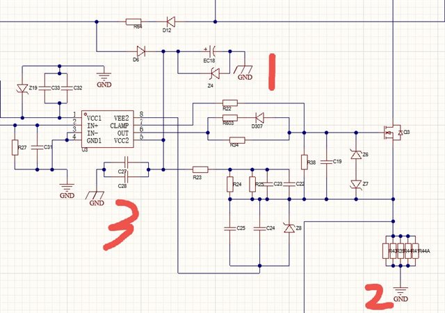
  • Hello Lydia, The schematic diagram below is the circuit design I referenced, which uses the UCC5350M driver chip to drive the SiC MOSFET. Since the chip requires the two sides (left and right) to not share a common ground, the supply voltage of VCC2 is provided by the auxiliary winding. Will it affect the circuit that the grounds at positions 1 and 3 marked in the diagram are different from the ground connected to the auxiliary winding that supplies power to the control chip's VCC? Also, does the ground at position 2 need to be consistent with the ground at position 1 on the right side of the driver chip?

  • Hello, regarding the new question you've raised, it has deviated from the original topic. Please post a new thread to inquire about your new issue concerning the circuit diagram review.