This thread has been locked.

If you have a related question, please click the "Ask a related question" button in the top right corner. The newly created question will be automatically linked to this question.

LM7481-Q1: LM7481-Q1 Circuit function inquiry

Part Number: LM7481-Q1

Hello:

I have a few questions:

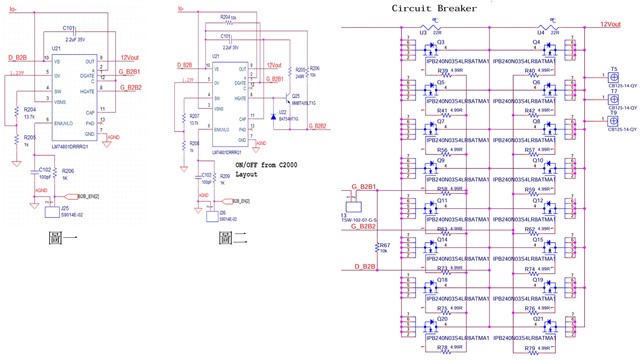
This circuit is a 400V-12V 3.6kW (TIDA-020031-3.6kW-DC-DC) circuit diagram downloaded from a website.

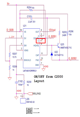
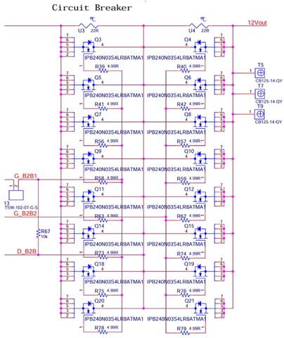
1. If I want the LM74801 to drive 16 switches, should I use the circuit in Figure 1 or Figure 2?

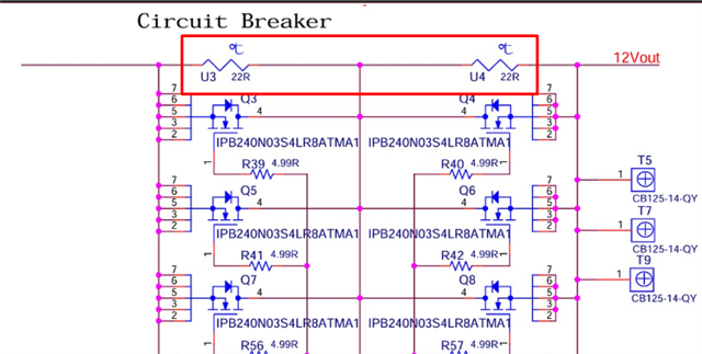
2. What is the function of the NTCs in U3 and U4 in the circuit diagram? The NTCs don't provide a signal to the MCU for detection.

Thank you.

  • 感谢您对TI产品的关注。
    我们正在核实您的问题,请等待我们的答复。

  • Hello:

    What is the current progress?

  • 1. Figure2 which says ON/OFF from C2000 will be better to use.

    2. Can you mark where the NTCs are?

  • 1.As shown in the red box in the picture, U3 and U4 are NTC (22R)

    2.*Should the C pin be connected to the VS pin?
       *Why doesn't the layout provided in TIDA-020031 use the C pin?

    3.Using the circuit diagram in Figure 2, Q25: How much drive current (NPN) should I use for the Hgate(G_B2) to drive eight switches in parallel? Can you provide     a calculation formula?

    thank you。

  • 1. NTCs seem to be pre-charge path.

    2. When the C pin of LM74801-Q1 is left floating, the reverse current blocking functionality is disabled. So, the device will allow reverse current flow through the MOSFETs. Now with the C pin floating, the device will have input reverse polarity protection, inrush current control and over voltage protection features only. 

    3. The current through NPN is dependent on the series resistor R205.

    If you want to limit the max current injection into the HGATE to 500 uA, then R205 = [(VIN(max)+15V)/500 uA]

  • 1. Should I use an NTC as a pre-charge circuit? What problems would that pose?
    2. If I need to drive eight switches in parallel, what is the minimum current required for the Hgate? Or how long should it be on?

  • 1. NTC may not be the best choice as the resistance will vary with temperature and have difference current at difference test conditions and hence not reliable.

    2. There is no hard and fast rule. It depends on system level expectations of switching time and the resistor can be scaled accordingly.