This thread has been locked.

If you have a related question, please click the "Ask a related question" button in the top right corner. The newly created question will be automatically linked to this question.

TPSI2140-Q1: TPSI2140-Q1应用问题

Part Number: TPSI2140-Q1
Other Parts Discussed in Thread: TIDA-010232,

TI FAE你好,

我这边基于TIDA-010232:高压电动汽车充电和太阳能中的绝缘监测 AFE 参考设计遇到了问题,描述问题如下:

1)我将固态继电器开关 TPSI2140-Q1和MCU分别放在不同的PCB上,之间的连线有20cm长

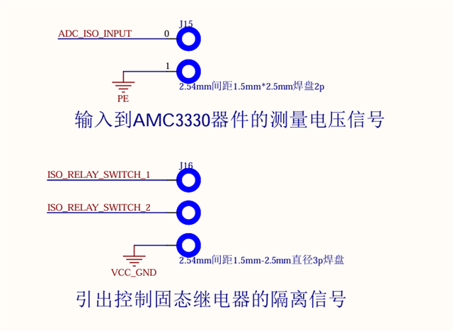
TPSI2140-Q1处的不平衡电桥原理图参考贵司的参考设计

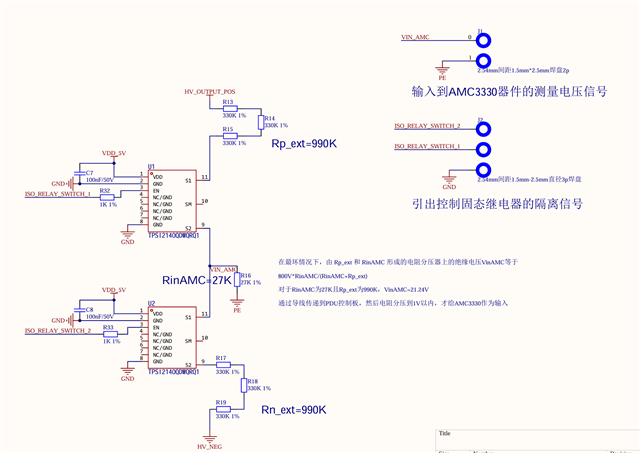
实际上R16并未焊接,而是留到AMC3300器件输入端口进行分压

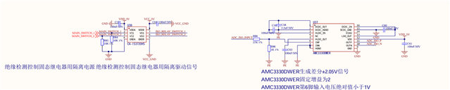
AMC3300在另一块PCB上,和MCU一起:

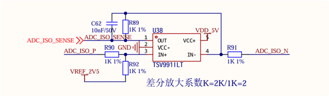
请不要介意,此处差动放大电路放大倍数实际为1。

拓扑结构如下所示:

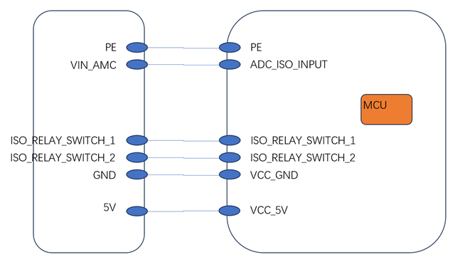
当我控制MCU,令ISO_RELAY_SWITCH_1和ISO_RELAY_SWITCH_2为高电平5V时,那么两个TPSI2140-Q1都应该导通,测量VIN_AMC和PE之间电压如下图所示

当TPSI2140-Q1侧HV高压母线不上电时:

当TPSI2140-Q1侧HV高压母线上电为30V时:

当控制两个TPSI2140都关闭时:

请问这是为什么会产生如此大的噪声?已知5V电源如通道1所示:

  • 您好,
    已经收到了您的案例,调查需要些时间,感谢您的耐心等待。

  • 您好

    What kind of probe are they using (single-ended vs differential)? Would recommend differential here, wonder if a single-ended probe would short the chassis ground (GND) to HV- and cause the measurement ripple. Maybe if the oscilloscope power minus is connected to chassis ground but the single-ended probe minus is connected to HV-.

    I think we can definitely check whether the TPSI2140-Q1 is causing this (I don't think it is) is by removing the top and bottom TPSI2140-Q1s and checking whether the measurement ripple still exists.

    For simulating the TPSI2140-Q1, we can model S1 to S2 as follows: