BQ25756: Question about BQ25756E

Part Number: BQ25756

Hello TI team,

Recently, I have been using the resistance-programmed BQ25756E as the output for the wireless power transmission (WPT) module. At the beginning, the initial power I input to the BQ25756E was lower than the normal working input power of the resistance-programmed BQ25756E during the constant current charging stage, and I gradually increased the input power value However, I found that at this time, the input terminal voltage of the BQ25756E was limited to 5V (the minimum input voltage I set). When I increased the power, this voltage remained unchanged, only the current rose, and the BQ25756E displayed off before the input power reached the normal working power. I have the following questions about this:


1.When I test the WPT module alone, both the output current and voltage increase. Why, after connecting the BQ25756E, does the voltage not rise but only the current when I increase the power?

2.What are the automatic shut-off conditions for BQ25756E? Is it based on voltage detection or current detection?


3. If I limit the minimum input voltage of the BQ25756E to a higher value (for example, 9V), will the BQ25756E always clamp the input voltage at 9V?

Thanks in advance!

  • Hi,

    We have received your post and the investigation will take some time. Thank you for your patience.

  • What are the input/output current and voltage settings of the BQ25756E? Please provide the resistance values and the desired settings.

    What kind of power supply are you using for the input?

    The BQ25756E is a battery charger IC, are you using the BQ25756E to charge a battery from the WPT?

    1. This sounds to me like the current is overloading the input source. We only clamp the input voltage at the ACUV setting when we are in VINDPM where we limit our current to stop the voltage from decreasing.

    2. This would be voltage detection. We can shut off due to current concerns, but we typically enter current regulation instead.

    3. Not always. The minimum voltage will be clamped at the ACUV when the device is in VINDPM (input voltage regulation). VINDPM occurs when the input source is being overloaded with current. We decrease the current drawn on the input to keep the input voltage from collapsing. If the input source is not being overloaded by current, the input voltage will be the nominal voltage of the input source.

  • Thanks for your reply!

    What are the input/output current and voltage settings of the BQ25756E?

    Max input current is 5A,input voltage is 5-30V,output current is around 0.48A in CC mode,battery voltage is 16.8V.

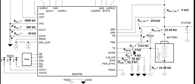
    the resistance values are shown in the pictures:

    What kind of power supply are you using for the input?

    I used the full-bridge rectifier output of the wireless power transfer system as the input for the BQ25756E.

    The BQ25756E is a battery charger IC, are you using the BQ25756E to charge a battery from the WPT?

    Yes,in the current testing phase, I am using the constant voltage setting of an electronic load to simulate a battery for testing.

    If the input source is not being overloaded by current, the input voltage will be the nominal voltage of the input source.

    I noticed that you mentioned nominal voltage. I would like to ask if this refers to the Input voltage-Nom in the BQ25756E resistor calculator? If so, how can I change this value through resistor programming (currently set to 20V in the calculator, but I do not see the corresponding programming resistor)? In my current testing, I have indeed observed that when my input and output power are matched, the input voltage of the BQ25756E becomes approximately 20V. Are these two factors related?

    We only clamp the input voltage at the ACUV setting when we are in VINDPM where we limit our current to stop the voltage from decreasing.

    How do I exit the VINDPM mode?

    VINDPM occurs when the input source is being overloaded with current.

    You mentioned that current overload caused the chip to enter VINDPM mode, but this situation only occurs when the output power of my rectifier is less than the corresponding input power of the BQ25756E. In theory, the stable current should be lower than the required value. Is this due to an excessive instantaneous current during power-on?

    Thanks in advance!

  • By nominal voltage, I probably mean the 20V. Nominal is just a term I mean to use for the default voltage of an input source. For example, a wall adapter plug may have a nominal voltage of 5 V when under normal operating conditions, but the voltage can decrease as the current load increases.

    Yes, this makes sense. The VINDPM tries to limit the input current to keep the voltage source from collapsing. When the output power increases, the input current needs to increase to provide enough power. If the output power increases too much, it can overload the input supply. When this happens, the current continues to increase, but the voltage decreases since the input supply is power limited. If the input and output power are matched, then this does not become an issue, and the input source can still be 20V.

    This only happens when the input power capability increases or when the output power decreases so that the input is no longer overloaded.

    This might be the case. Does setting EN_CHG = 0 and then EN_CHG = 1 help improve the situation?

    Also, MPPT is for solar panel operation, but it might be good to try out the MPPT algorithm to find the maximum power capability of the BQ25756E.