This thread has been locked.

If you have a related question, please click the "Ask a related question" button in the top right corner. The newly created question will be automatically linked to this question.

LM5164: How to select the capacitance value of Cout (output capacitor) for LM5164? And what is the correct calculation formula?

Part Number: LM5164

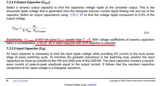
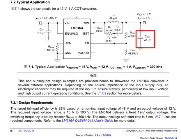
In Section 7.2 (Typical Examples) of the datasheet, it states that Vout = 12V and Cout = 47uF. However, according to the formula provided in Section 7.2.2.4, when working backwards from the noted parameters, it results in Vout being approximately 5V with Cout = 22uF, which is clearly incorrect. How should the correct formula be applied to calculate the value of 47uF? 
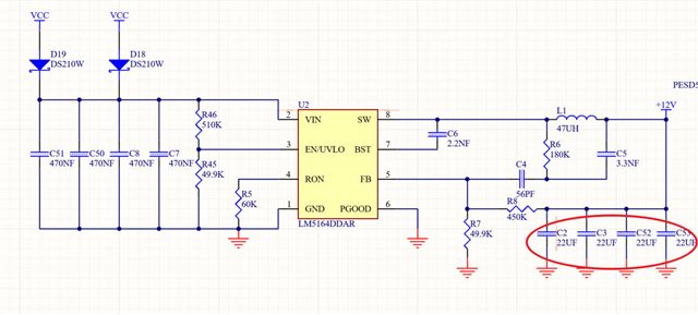
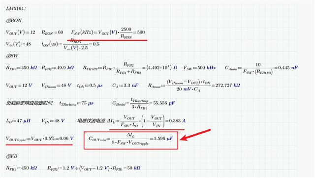
In an application solution, the calculation results in a Cout of only approximately 1.6uF, which differs significantly from the actual configuration of 4 parallel 22uF capacitors. What is the appropriate value for Cout in this case? Additionally, is it recommended to use multiple capacitors in parallel as Cout?


  • Hi,

    We have received your post and the investigation will take some time. Thank you for your patience.

  • Hi,

    The Formula is correct, its evaluation for the values used is a little off. 

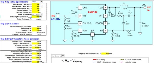
    Kindly use the excel tool LM5163-LM5164DESIGN-CALC Calculation tool | TI.com to calculate Cout_min.

    Higher capacitor value is chosen to have a good margin even after the DC bias effect/ derating of the capacitance value. For example, the derating of capacitance value [ceramic capacitors] of 25V rated 22uF capacitor can be ~60% at 12V. 

    Also, usually Cout is chosen to have a good margin over worst case minimum capacitance value to reduce overshoot during load transient.

  • Thanks for your quick reply. 

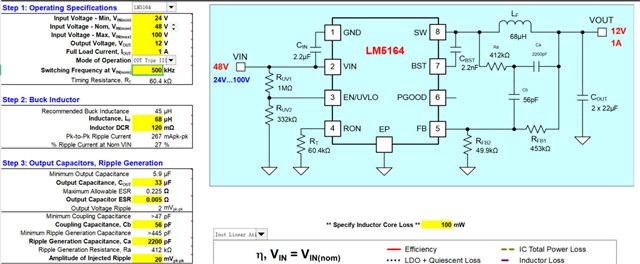
    I used the design tool you mentioned, and the calculated output capacitor Vout is 33uF. However, the design diagram on the right uses two 22uF capacitors in parallel.

    Could you please tell me why this is the case? Should I use two 22uF capacitors in parallel when designing?

  • Hi,

    Thanks for your quick reply.

    I used the design tool you mentioned, and the calculated output capacitor Vout is 33uF. However, the design diagram on the right uses two 22uF capacitors in parallel.

    Could you please tell me why this is the case? Should I use two 22uF capacitors in parallel when designing?

  • Please follow the approach with your parameters taking into account DC bias effects of ceramics, thanks.