BQ4050: Configured with fixed EDV0/1/2; SOC is not updated when the voltage threshold is reached.

Part Number: BQ4050


Hello TI Experts,

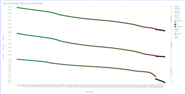
We have designed a 3S3P NMC battery power management solution using the BQ4050. The BQ4050 was configured for the fixed EDV mode with set voltage thresholds for EDV0/1/2. However, during actual testing, the SOC did not get corrected based on the configured EDV thresholds. Instead, it triggered the pack's CUV (Cell Under Voltage) protection while the SOC still showed around 3%, as shown in the attached test data and configuration files. Could you please help identify where the issue might be?

Additionally, under normal circumstances, is EDV correction a fast and smooth process, or does it happen as a direct jump?

Thank you!

电池放电曲线.xlsx

  • Hi,

    We have received your post and the investigation will take some time. Thank you for your patience.

  • HI 

    Have you identified the cause? Thank you.

  • HI 

    Have you identified the cause?

    Thank you.

  • Hi,

    This case is currently under investigation, and we will contact you with the results shortly.

  • May I ask if there have been any analysis results? I have been waiting for your reply! Thank you.

  • Please wait a little longer. I will inform you as soon as there is any update.

  • Hi 

    It has been 11 days since I submitted my inquiry, but I have not yet received a response. I hope you can understand my urgency—please prioritize analyzing the cause of the issue and provide feedback as soon as possible. Thank you!

  • Hi,

    I'm very sorry for this. However, due to the complexity of the issue, it may take some more time.

  • Hi,

    1st. Make sure your CUV is correct for your application. It might be too high if SoC hasn't' reached 0%.

    2nd. Usually, with CEDV, part will update after you pass the EDV thresholds. The update impacts the FCC. See 6.3 section on TRM

  • Hi 

    Thank you for your response. However, your reply did not resolve my issues:

    1. The battery's undervoltage threshold was provided by the battery supplier after rigorous testing, and this value is reasonable. I have uploaded the battery configuration parameters and test logs for your reference.

    2. I have already studied Section 6.3 of the TRM but could not identify the reason why the CEDV smoothing function is not working. This is precisely why I sought your assistance. Please help confirm the root cause!

    Thank you!

  • Hi,

    Can you please share the .gg file? I dont see it attached on the thread.

  • Hi

    I have already attached the test logs and gg file to my issue. Is it possible that you cannot access them? I am uploading them again. Please review and confirm as soon as possible.

    Thank you.Battery Discharge Curve.xlsx

  • Hi 

    It's been a while since I've heard from you. May I ask about the progress of the analysis? Thank you.

  • Hi,

    Please wait a little longer. I will inform you as soon as there is any update.

  • It has been over a month since this issue was submitted for analysis, but TI has not yet provided possible causes or useful suggestions. I hope the analysis progress can be accelerated. Thank you.

  • Hi

    Several more days have passed. Are there any updates on the analysis?

    Thank you.

  • Hi,

     I looked at your .gg file and data closer. I can see the CUV threshold is 2.9V and indeed, CELL3 reached 2.9V. There seems to be a big difference between Cell3 and (Cell1 & cell2) . Please consider checking for leakages and using cell balancing for your application.

  • Hi,

    The observed phenomenon is real-time. We have inspected this battery and found no signs of leakage. The balancing function is also enabled. This is precisely what puzzles us:

    1. The designed battery capacity is 9000mAh/9720cWh, and the design voltage is 10800mV. The abnormal parameters shown in your screenshot were unexpectedly modified by the test equipment during charge/discharge testing. The reason for this modification is still unknown.

    2. As shown in the attachment, why did the SOC smoothing fail to trigger when Cell3 voltage dropped to EDV2/1/0 thresholds? Could this be related to the accidental modification of the design capacity and voltage mentioned above?

    3. According to our design parameters, EDV correction should be triggered when the lowest cell voltage among Cell1/2/3 reaches 3354mV (EDV2), at which point the fuel gauge should smoothly adjust SOC to 9%. When the lowest voltage further drops to 3205mV (EDV1), SOC should be smoothly corrected to 3%. Finally, when the lowest voltage reaches 3000mV (EDV0), SOC should be smoothly adjusted to 0%. However, no such SOC smoothing process was observed in practice. Please confirm the root cause.

    4. The significant voltage deviation of Cell3 compared to Cell1/2 is another point of confusion. We have carefully analyzed the cells and BMS from end-user returns with large voltage deviations but found no abnormal leakage. The capacity differences among Cell1/2/3 are minimal. We also noted that voltage deviations consistently occur in Cell2 and Cell3, while Cell1 has never exhibited this issue. What could be the potential cause? Is it possible that the balancing function for Cell2 and Cell3 is abnormally activated? (Our system is designed to read battery status information every 7 seconds.)

    As this issue involves end-user complaints, we kindly request an expedited analysis. We look forward to your prompt response. Thank you!

  • Hi,

    The SOC smoothing is working as intended.  I double checked with the data log you sent. The SOC reported matches the EDVX threshold you mentioned. The EDVX threshold are to respect to the total BAT voltage, so if your EDV2 threshold is 3354mV then the actual voltage which the gauge will report 9% will be 3 cells * 3365mV = 10095mV. What happened is that the CUV got triggered before the battery pack was able to reach EDV0 which is set to 9V. Last reported voltage from the gauge was 9.56V.

    Based the gg file. The cell balancing did occur on the CELL1 and CELL2, but not in cell3. This could be the issue. Cell3 is not getting time to be balance, so it getting discharge at a much faster rate than the other two cells. The datalog shows how all three cells start at the same time, but they start to deviate overtime. Please try using different cell balancing settings if possible.

    Cell_balancing_Configuration.pdf App note.

  • Hi 

    Thank you for your response. I'm unable to view or download the PDF file you provided due to permission restrictions. Could you please advise where I can access it?

    I believe the current configuration uses single-cell EDVx smoothing method rather than the pack voltage method you mentioned. In the BQ4050 TRM Page 52's Pack Configuration description, where is the EDVV bit located? I couldn't find any description about the EDVV bit. Is it possibly the EDV_PACK bit on TRM Page 123? If so, we have configured EDV_PACK=0, which should correspond to cell voltage mode. What could be the reason why this isn't taking effect as expected?

    How should we evaluate whether to use cell voltage method or pack voltage method for EDV smoothing?

    Thank you.

  • Hi

    I send you the pdf by private message.

  • I have received it, thank you!
    Please help confirm the following issue: Our configuration follows the single-cell voltage calibration CEDV method (EDV_PACK=0), not the pack voltage method. Why hasn't our setting taken effect? Thank you.

  • May I ask if there are any answers to the questions above?

    To summarize, I hope to achieve CEDV correction based on the minimum cell voltage. Is this possible? If yes, what modifications are required in my current configuration? Thank you.