Part Number: PMP41009
Other Parts Discussed in Thread: UCC28740, , PMP41031
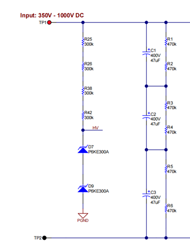
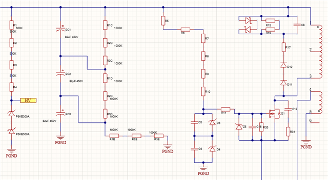
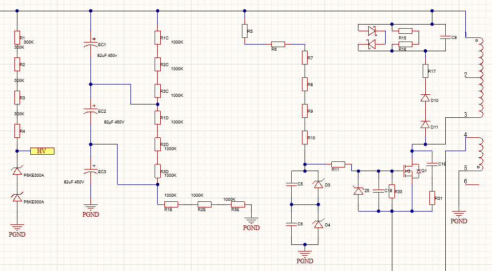
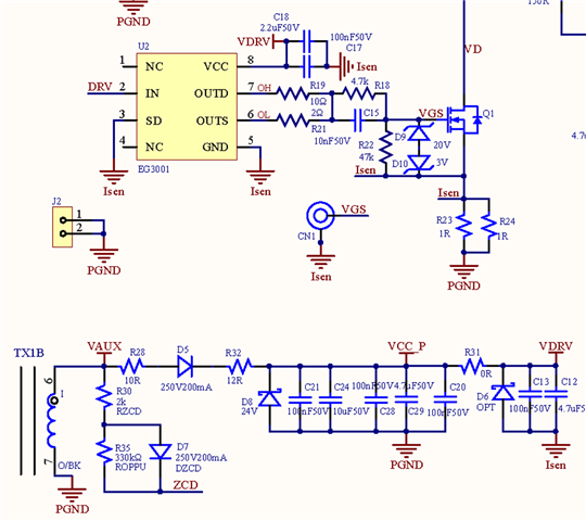
Hello, I am debugging a self-designed flyback switching power supply with an input of 90-900VAC and an output of 24VDC. I use the UCC28740 chip and adopt the relevant power supply circuit from the PMP41009 design. Why is it that when the input is 220VAC, the voltage after rectification is 328VDC, the measured voltage at the HV pin is 12V, the chip fails to work normally, and the voltage at the VDD pin is only 1.3V? No changes have been made to the circuit. Below are the relevant power supply circuit from the PMP41009 design and the power supply schematic diagram of my input voltage after rectification. The turns ratio of the transformer is 20:5:6, Rvs1=160kΩ, Rvs2=24kΩ.Could you please advise on how to solve this problem?I also asked this question last Monday, but when replying to your inquiry, I couldn’t upload images or send messages at all, and it’s only now that I can do so.