RE: TIDM-02013: Regarding the overcurrent protection in Lab 3


I have currently conducted three experiments by modifying the relay closing conditions and AUTOSTART judgment criteria:
  1. The relay closes first (when Vbus = 80V); after the program runs (by increasing the input voltage until Vbus = 100V), the voltage is boosted, triggering overcurrent protection.
  2. After boosting the voltage (when Vbus exceeds 90V) and reaching the relay closing condition (Vbus = 150V), overcurrent protection is triggered.
  3. After boosting the voltage (when Vbus exceeds 90V), the relay (set to close when Vbus exceeds 250V) does not close, and the voltage rises normally.
However, the PTC resistor currently in use definitely cannot operate under load for a long time. I am now trying to replace the PTC resistor with a 20-ohm NTC resistor, hoping for success.
  • Hello!

    We have received your case and will take some time. Thank you for your patience.

  • Replacing the NTC resistor did not work, as the circuit board still activates overcurrent protection the moment the relay closes. When I set the relay to never close, the voltage can be boosted, but this clearly deviates from the original design intent. 

  • You should not use NTC resistor. Also may I know what type of over current trip did you see. If it's output DC over current trip, did you try disabling it.

    I have also copied our SEM team if they have any input on this.

  • Currently, I'm encountering the issue of boardStatus_OverCurrentTrip_Ph2_H. I attempted to disable the overcurrent protection, but this led to the explosion of C160 and C155. The output DC bus voltage was approximately 320V at the time of the explosion.I currently don’t know the cause of the explosion, so I dare not disable the overcurrent protection again. Why shouldn’t NTC resistors be used?

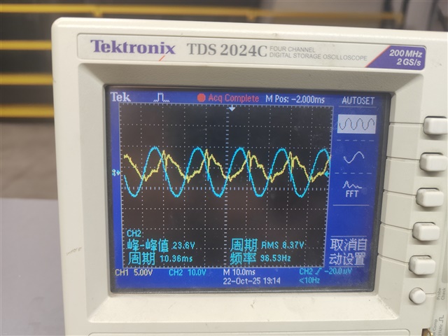
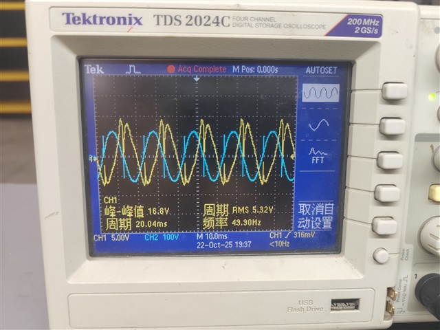
  • When the relay closes upon meeting the closing conditions, an overcurrent fault occurs during subsequent voltage boosting. I set the relay's closing condition to 1000V (intended to keep it open), and replaced the NTC resistor with one having much higher voltage and current ratings. When the input voltage is 75V, it can boost to approximately 276V, which is outside the expected range of 180V. The input current and voltage do not follow each other, and the input voltage has spikes, with the input current leading the voltage by roughly 90 degrees. Then I connected a 500-ohm resistor on the output side, and the spikes became even larger. In the figures, CH1 represents current at 5A per division, and CH2 represents voltage at 50V per division. Figure 1 shows the state without a connected load, and Figure 2 shows the state with a connected load.

  • Why are the input voltage and input current not in phase?