SLUC222: Simulation of PSFB converter

Part Number: SLUC222
Other Parts Discussed in Thread: UCC28950, TINA-TI

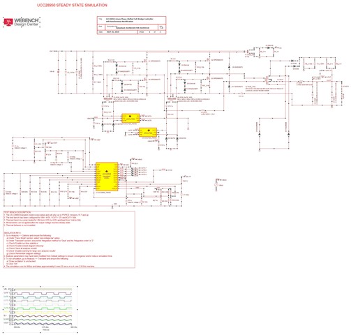
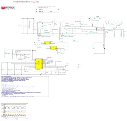
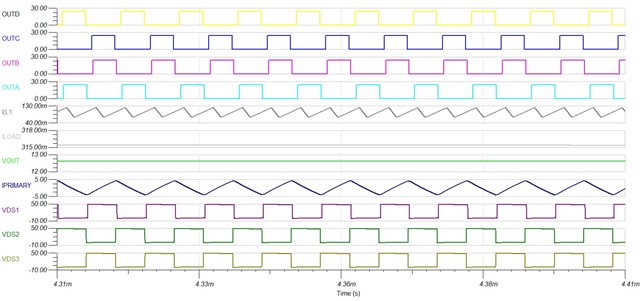
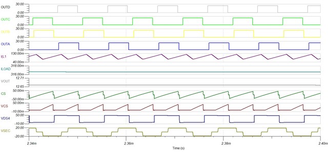
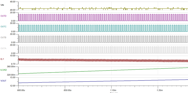
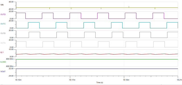
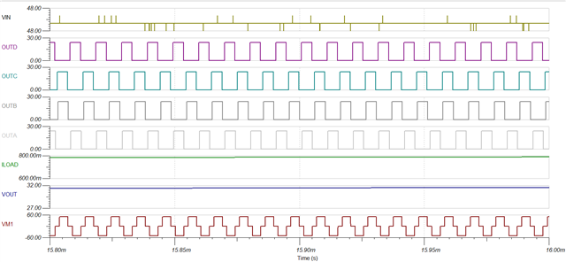
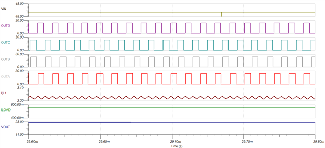
I am simulating a PSFB converter using UCC28950 in TINA-TI. My input voltage range is 43V to 58V and output voltage is 240-385V ,output power is 4KW. I am seeing an issue with the simulation output. The converter  output voltage goes to 12V instead of 385V.

Issue: The output voltage doesnot change,It remains on 12V

image.png

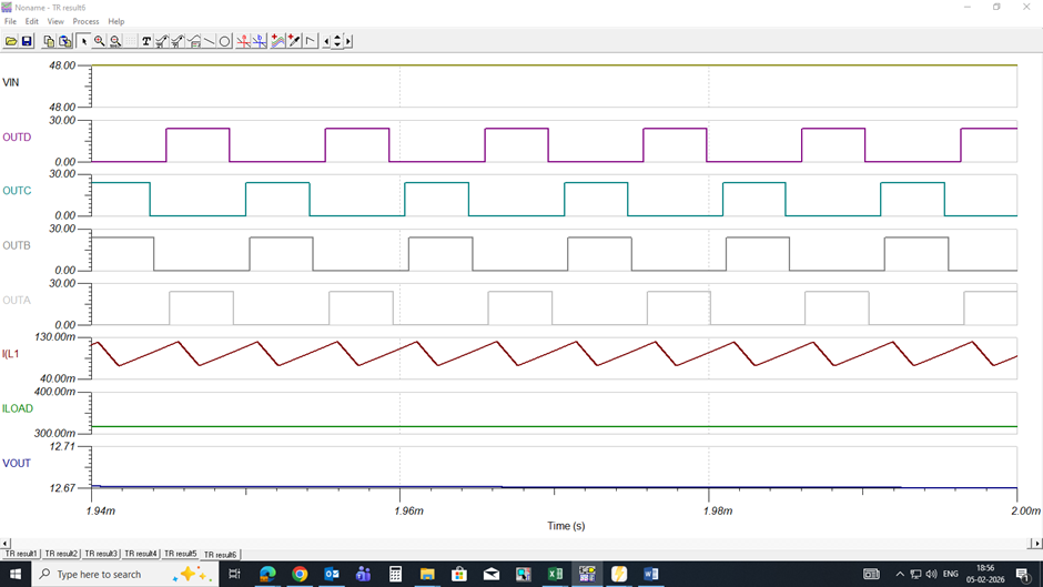
Expected behavior: The converter should regulate at 365V as per the design tool for an input of 48 V.

What I have tried:

– Checked transformer turns ratio

– Adjusted compensation values

Simulational and design files are attached.

PSFB4kwtina.TSC 

PSFBdesign4kwfinal.xlsx 

Could you please help for the detailed design and simulation using TINA TI simulation tool. 

Thank you

  • 您好

    已经收到了您的案例,调查需要些时间,感谢您的耐心等待

  • 您好

    不知为何我无法打开你的TINA-TI模型。能否请你分享一下原理图。

    审核了Excel计算器,若使用的补偿值与您在Excel中给出的相同,我建议更改补偿值,因为根据您的设计阶段,裕量略偏低(45度)。推荐值为:- RF=1870kOhm CZ=0.08nF CP=8.20pF

    同时检查CT输出是否跟随主电流。要检查电流控制回路是否存在问题,请尝试在禁用峰值电流模式控制的情况下进行模拟,通过Rsum电阻器将Rsum引脚连接到Vref。

    如果问题仍然存在,请告诉我。如果我能跑,我会尝试TINA模拟。同时,如果你能分享初级电流、桥式开关的VDS、CT输出、SR输出电压的原理图和波形,那就太好了\

  • Hi,

    This is the schematic diagram. 

  • Please find attached the schematic and waveforms for the primary current, bridge switch VDS, secondary output voltage, CS output, and output load current.

    Update-

    -The compensation values were updated as suggested; however, the output voltage rises to 12 V .

    -The CT output does not follow the main current, as shown in the waveforms.

    -I also simulated with peak current mode control disabled by connecting the Rsum pin to Vref through the Rsum resistor, but the issue still persists.

    Please let me know your feedback.

    Thank you

  • 您好

    您的二次电压与预期不符,匝数比为8:100时二次电压应该更高。48个输入的次级峰值电压应为600V,而不是20V。这可能是因为匀场电感器(L2)。您使用了26uF的匀场电感(值甚至超过磁化电感),根据您的计算器,初级侧不需要匀场电感。只需缩短匀场电感或使用非常低的电感值,然后再次尝试模拟。这将解决你的问题。

  • Hi,

    Thank you for your suggestion.

    I removed the 26 µH shunt  inductor from the primary side and re-ran the simulation as recommended. However, the secondary voltage still does not boost as expected. The output remains low, and the issue persists even without the balancing inductor in place.

  • 您好

    In the latest waveforms, the output voltage and current appear to be building up, and the soft start is set to 15 ms. However, the measurement was taken at 1 ms. Could you please confirm whether the voltage is still not building up even after 15 ms?

    To help narrow down the debugging process, could you please check the output voltage of the full bridge with respect to the secondary output voltage? This will help verify whether the input voltage is being properly transferred to the secondary side. If it is not, then the issue is related to the transformer magnetics