This thread has been locked.

If you have a related question, please click the "Ask a related question" button in the top right corner. The newly created question will be automatically linked to this question.

TPS92520-Q1: The spike of my current waveform is too High

Part Number: TPS92520-Q1

IC solution: TPS92520Q1

Vin:              48V

V_loading:    ADB(Adaptive Drving Beam) 118 Pixel

I required:    1 Amp ( L = 47uH, Cout = 0.1uF + 0.01uF+1u)

_____________________________________________________

My question:

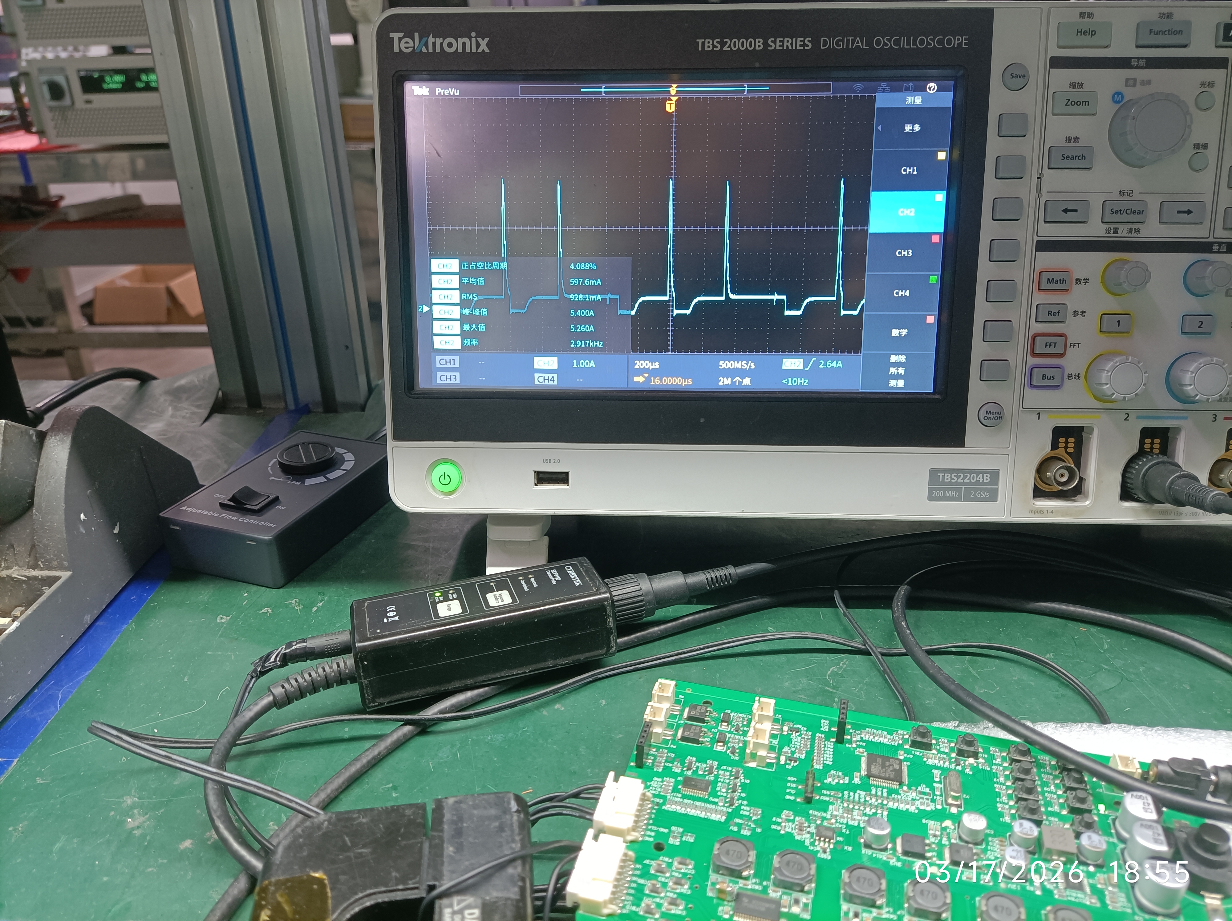
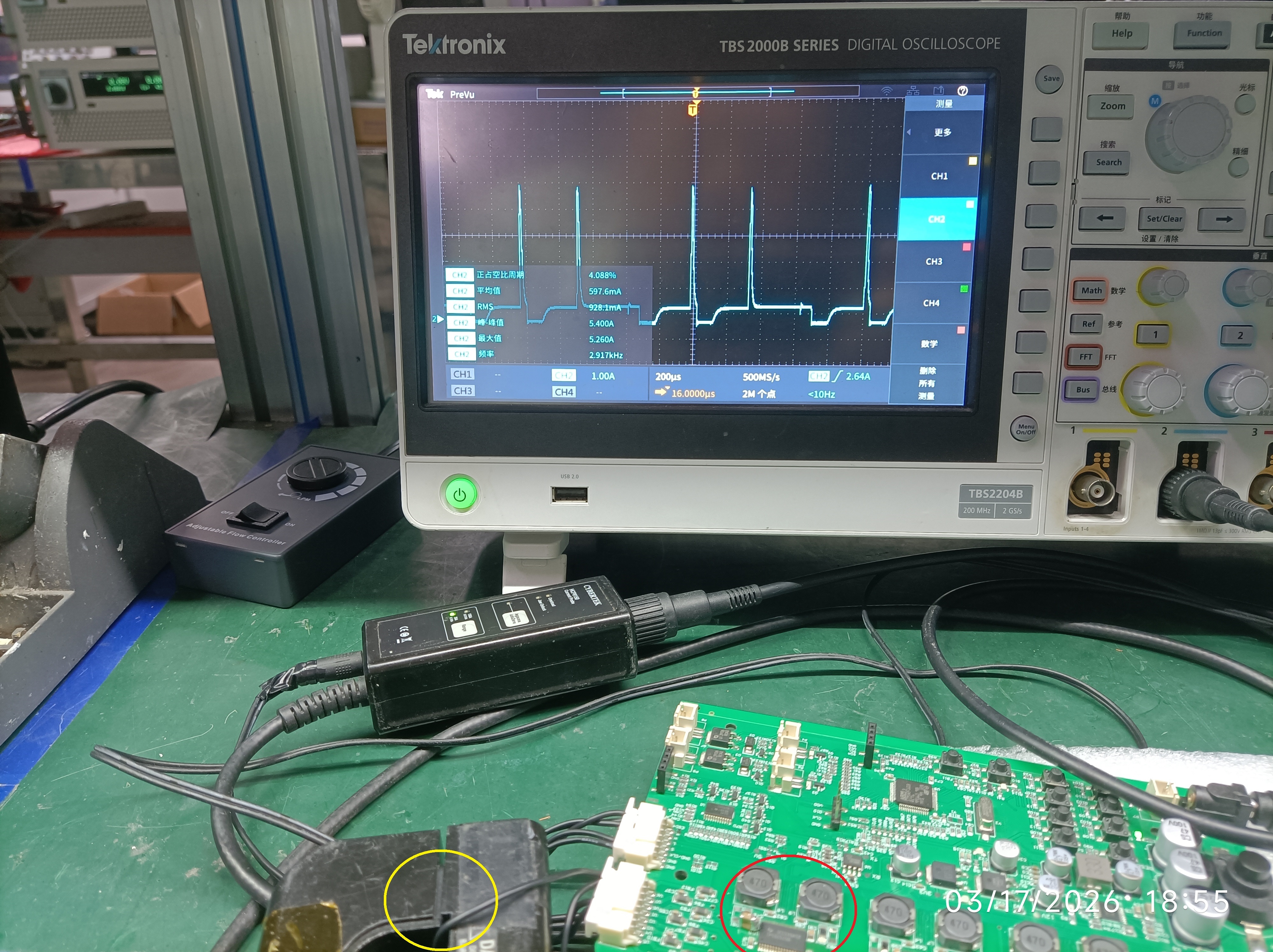
1. Why is my current waveform spike going so highly while the waveform in the datasheet looks              smoothly. (My waveform will be shown at the end of this box)

2. I tried to add a 1uF cap after the sensing Resistor

    a), As you can see in the snapshot, the voltage drop is accaptable, but the current spike goes to 4A           or even higher.   

    b), The current will go down to 0 without a 1uF Cout, whose width is around 10us

3. I tried to add a 1 uF cap before the sensor, however, the circuit failed to output current totally.

4. I tried to make the inductance larger(from 470uH to be 660uH), but nothing noticable happened.

5. What should I do to improve my waveform to make it go smoothly, as it shown in the datasheet?

Thanks and Best regards

TPS92520q1.jpg

  • Why is there no one wanted to answer my question?

    What's wrong?

  • Hello,

    You need to give me a schematic and or a block level diagram of what you are trying to do. I also need the register setting used on the TPS92520.  Are you writing your own code or are you using the GUI?  If so, then you can give a register dump.  I don't know why you are using 470uH, unless you are using a really low switching frequency.  

    You need to also tell me where you are using the current probe in the schematic for you test setup.  

    Please share your project information and company information.

  • Dear Alice

    1. I can't access the schematic freely, that is why I didn't upload it last time

    2. Frequency = 437k, (I was told by the SW engineer, who wrote the code)

        a. I don't konw why they choose 473K, and why they choose 470uH

        b. Does that matter for the current spike? (As I experienced, the Cout is paramount factor of the Current spike)

        c. According to the waveform of my snapshot, coud you confirm that?

    3. As I said, the probe is locating after the Resistor. And also, you can see it at the bottom side in the snapshot.

         (or Please refer to the snapshot in this box. TPS92520 was highlighted in Red circle and the current probe was highlighted in Yellow circle)

    4. All I want to do is to output a stable 1 amp current for my ADB LED matrix, using TPS9250.

    5. According to my company's policy, I can't share the project info here. (Please refer to my profile, if you could see it)

    Thank you, Alice

    Best regard

    Churbill

  • Unfortunately, we are unable to provide further recommendations based on the current information

  • Dear Vivian

    1, What info do you want (Schematic? I can't share it here as I said.  Quite the same as it described in the datasheet)

    2, After having bebugged for several days, I learned a lot from the spot and come to appreciate the difference between superficial and essential.

    3, For the time being, I have a new question: There are 4 identical widgets in my project, but none of the senesing resistor is at the same value, while the output current is the same. (In other words, the output current is various significantly using the same value sensing resistor).

    Thank you, Vivivan!

    Best regards!

    Churbill