Part Number: BZX884C18V
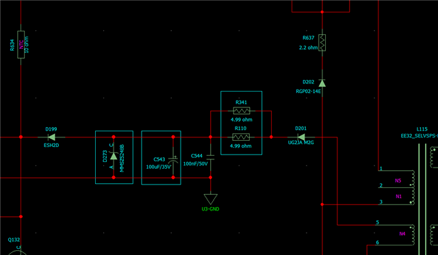
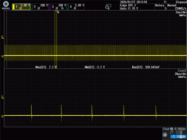
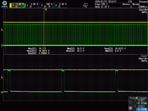
Hello TI engineer,In my flyback power supply, the auxiliary winding voltage is rated 18V, but rises to 21V under heavy load.I tried a series resistor(2.5ohm) + Zener diode (BZX884C18V)clamp to limit the auxiliary voltage, but the voltage still reaches 21V.as shown in the waveform below.When measuring the current through the series resistor, only a short pulse current appears, as shown in the waveform below.


But I don’t understand why the Zener diode isn’t damaged and shows no voltage regulation, behaving like an open circuit.
When a Zener diode operates in the reverse breakdown region, its dynamic resistance is extremely low (only a few ohms or even milliohms). Once the voltage across it exceeds VZ, the reverse current IZ should surge without limit until the power dissipation PZ = VZ × IZ is much higher than PZM, causing instantaneous thermal breakdown and physical destruction of the PN junction.