This thread has been locked.
If you have a related question, please click the "Ask a related question" button in the top right corner. The newly created question will be automatically linked to this question.
Hi
DCP021212是10.8~13.2V输入11.4~12.6V输入的2W隔离DC/DC转换芯片,故5V输入是不对的,需要用12V输入。
电路图请参考datasheet: http://www.ti.com.cn/general/cn/docs/lit/getliterature.tsp?genericPartNumber=dcp021212&fileType=pdf 第七页Figure 8.
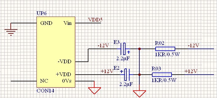
Vin引脚需要增加一个2.2uF或者更大的陶瓷电容,layout上尽量靠近芯片Vin脚。另外连接上电容E3/E2都是接到GND的电容,R02/R03接法是是否画错了,都接到GND了。 关于同步脚,如果单个芯片使用,需要悬空。
恩 知道了
你说的电阻问题:
是电阻R02/R03是我接的假负载 ,因为这个没有稳压功能,要不然输出电压太高