This thread has been locked.

If you have a related question, please click the "Ask a related question" button in the top right corner. The newly created question will be automatically linked to this question.

TI_ each chip solution, board file want to add test point for ICT


Hi all,

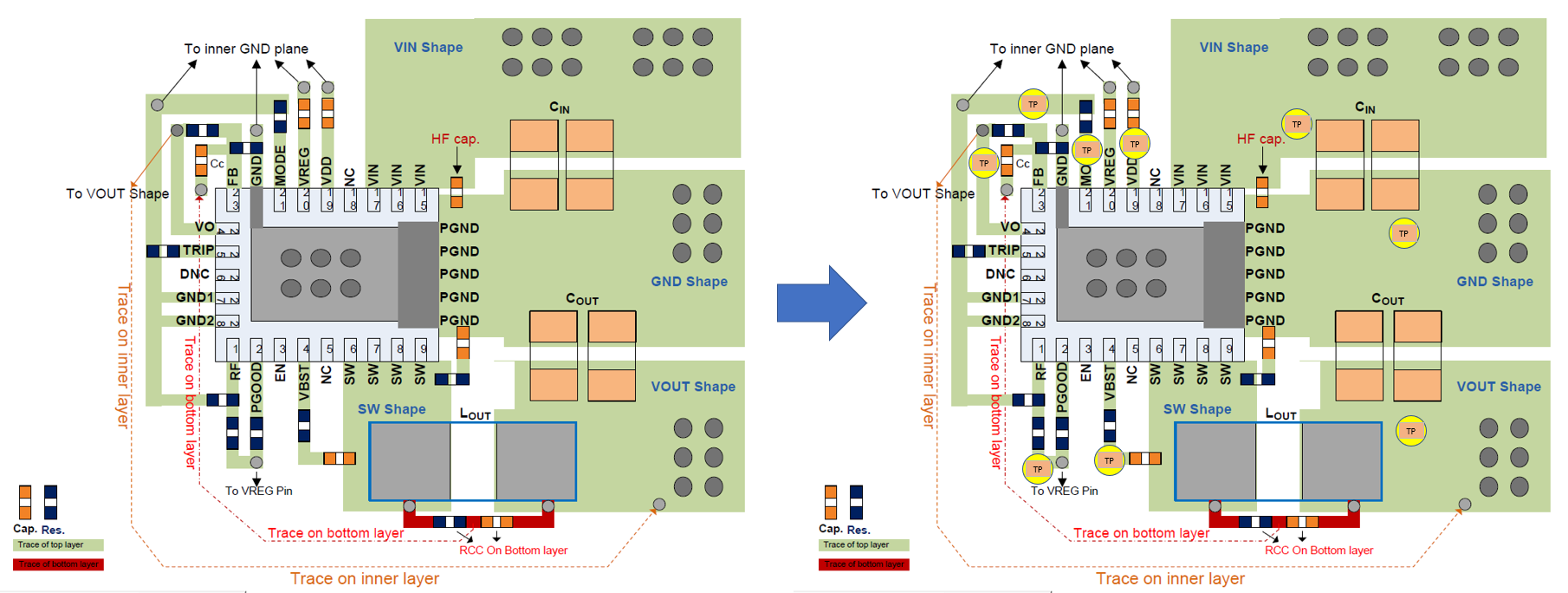
Regarding of test point, that we want to implement it for ICT function test in factory.

About TI’s each chip solution, do you have any concern which traces should not be added test point, example h/l gate trace, phase, sensing …  

I think should added test point at source input voltage and end output voltage side for ICT only, right?

or don't care it!

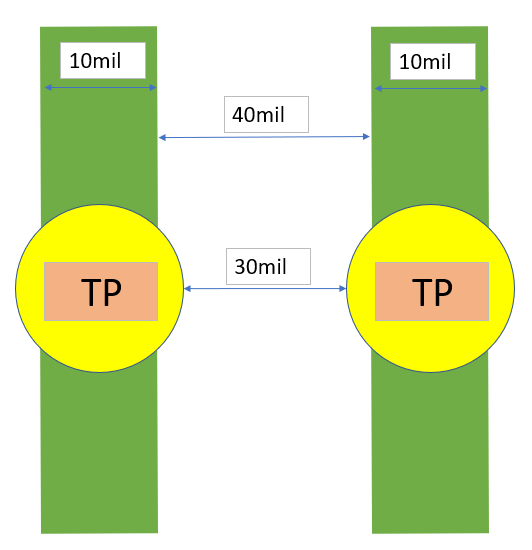
(1)The test point diameter is 20mil, if layout trace less than (ex : 10mil) whether can be add it?

(2)Will the ICT test cause ESD breakdown?

  • I think,you can test each function on your board by needle bed or manipulator.
    On test pipeline, the testing point can go 0.1mm, but you need high performance test point for your system.
    The limited is from point mechanical precision and life.
  • Hi, KW X

    I’m worry added test point trace is too close to the adjacent trace.

    Originally, the two traces were 10 mils wide and the distance between them was 40 mils. After adding the test points (20 mils), there is 30 mils left. Is there any hidden worry about the reduced distance?

  • Hi

       ICT针对的不是IC,而是真个电路,所以你需要对整个电路评估后确认ICT测试点,并在PCB设计中体现出来。

      (TI的芯片一般不会单独就IC给出ICT测试方案,ICT重点在于测试短路短路,一般覆盖整个电路)