Part Number: LMG1210
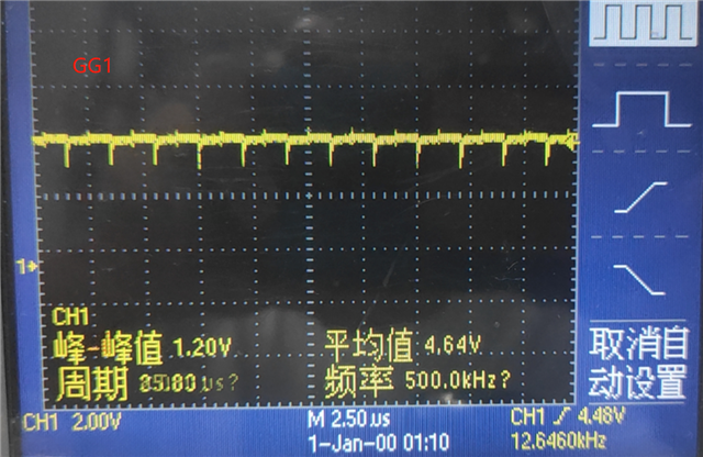
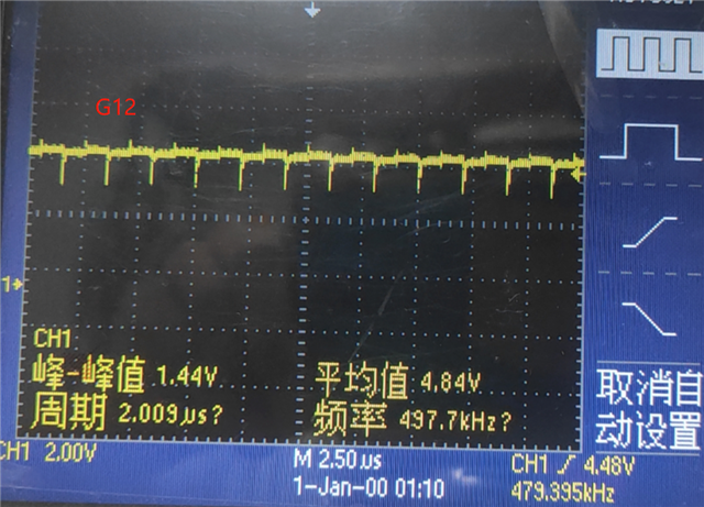
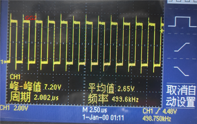
When I send 50% duty cycle, 500KHz complementary pulse signal to the hi and Li of lmg1210, and add epc8010 chip to the back end, the continuous pulse waveform will be output and flicker. How to solve this problem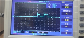
Part Number: LMG1210
When I send 50% duty cycle, 500KHz complementary pulse signal to the hi and Li of lmg1210, and add epc8010 chip to the back end, the continuous pulse waveform will be output and flicker. How to solve this problem

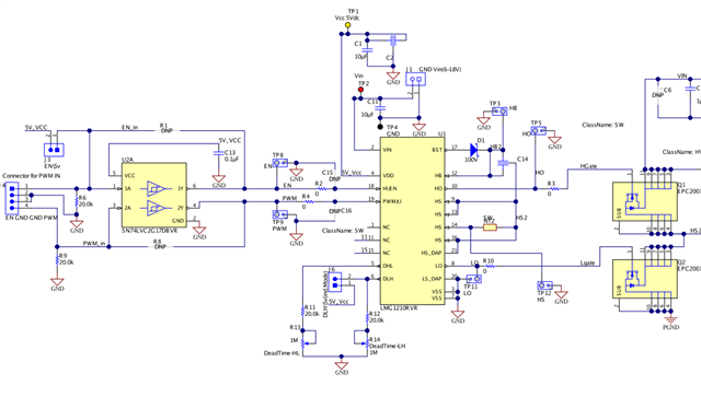
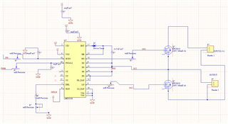 This is my schematic diagram. I have spent much time.but I don't find any problem. Can you help me .Thanks you!