Part Number: TPS6594-Q1
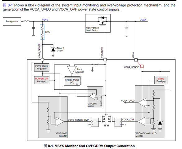
EQ1:The data sheet mentions: "Current through input protection FET: Between VSYS_SENSE & VCCA should be lower than 15A", can you describe the detection mechanism of the input current overcurrent protection in detail?

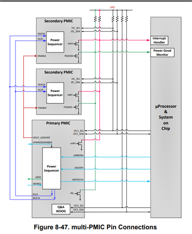
EQ2:In the multi-PMIC synchronization state, how to analyze the fault code transmitted by the Secondary PMIC through SPMI from the I2C2 communication transmitted from the Primary PMIC to the MCU?
EQ3:What are the I2C1_ID and I2C2_ID of the three materials TPS6594C41-Q1, TPS6594C31-Q1 and TPS6594133A-Q1?
EQ4:If the output ports of LDO1~LDO4 pins are used as external voltage monitoring, what is the output current threshold to start over-current shutdown? And is the threshold configurable?
EQ5:Can TPS6594-Q1 read the specific values of input and output voltage and input and output current, and feed back the specific values to the MCU through I2C2?(Instead of just feeding back a fault interrupt signal through I2C when the input and output current or voltage range is outside the threshold range.)
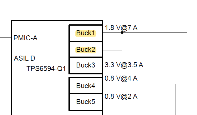
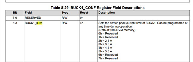
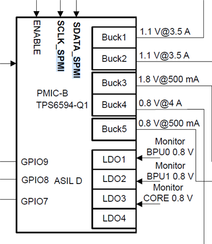
EQ6:As shown below: BUCK1 and BUCK2 in multiphase configurations,can the overcurrent monitoring threshold reach 7A?
The register configuration in the data sheet seems to be only from 2.5A up to 5.5A for a single channel. The combination of the two BUCKs becomes a multi-phase adjustment mode. Will the over-current interrupt protection be triggered if the current reaches 6.5A?Is it convenient to give a description of the ILIM protection mechanism?