I'm designing a Buck converter with LM25141, with 12v input and 3.3v output.
Following Webench designer and datasheet, I tied FB pin with Internal LDO output.
But it's outputing 1.5~1.6v now, and I soldered 3 PCBs in total and two of them got 1.5~1.6v, the third one got.. 3.23v, after I unplugged and re-plugged the input voltage in, it's dropping!
From 3.23v, to 3.13v during the second time... and 3.09v the third time... and 2.90v at last
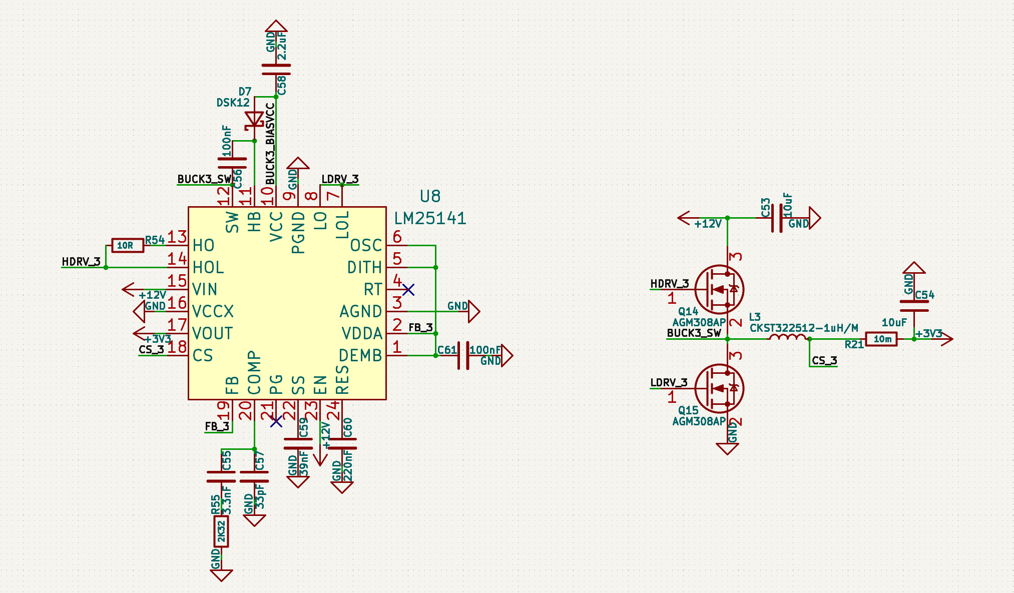
THATS WEIRD! and here's my schematic
我正在用LM25141设计一个Buck转换器,输出12v,输出3.3v
根据webench和规格书的说法,我把FB脚和内部LDO输出接在了一起
但是它现在输出了1.5~1.6v... 我一共焊了三块PCB,其中两块输出了1.5~1.6v 第三块在一开始的时候输出了3.23v 但是当我把输入电源拔掉再插回去... 3.23变成了3.13 又变成3.09 拔插了几次以后最后变成了2.9v 如果我再拔插它应该还会下降...
这里是我的原理图 这也太怪了...