

I use the “SwitcherPro Desktop”software to design .
My Vin=23~25 Vout=27V IOUT=0.1A
I have different resistance from 105 mR to 100mR (R13)
MY Loads is double 12v’s battery.
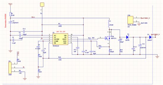
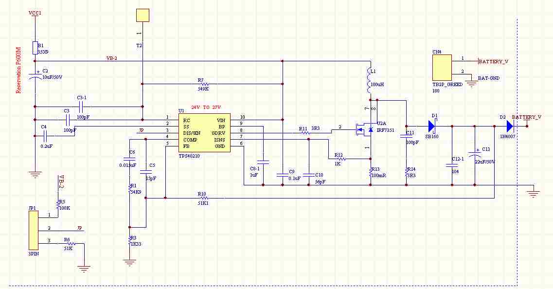
My circuit as below
My Vout will connet to 24v battery to support battery electrify.
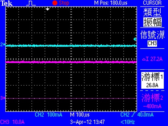
When I no connect the battery (NO LOAD).
My Vin is 24V , Vout is 27v ( red wire),Iout is 0A(blue wire) . as below .
It’s OK.
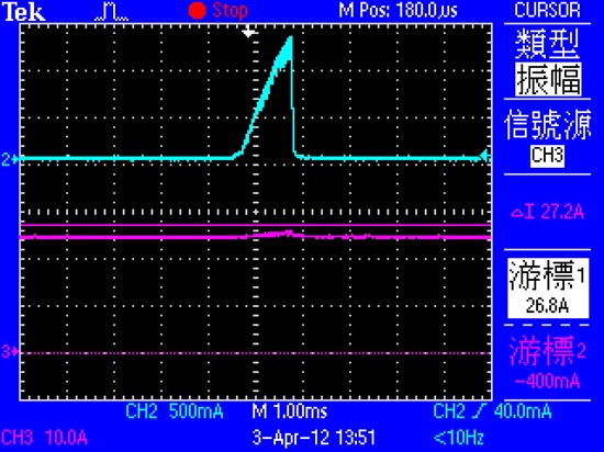
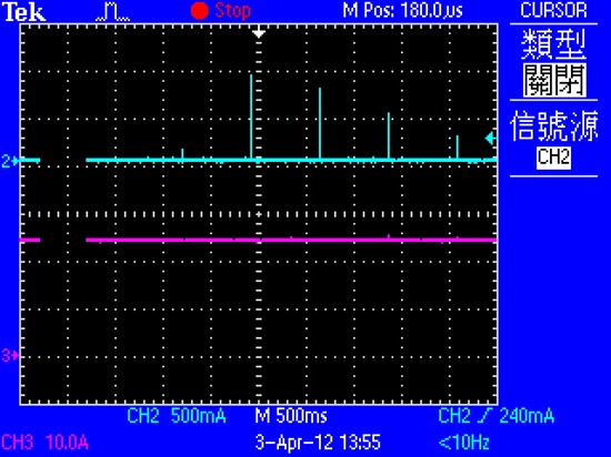
But when I connect the battery . (Connect LOAD)
My Vout from 27 down to 24.4v and the IOUT (OUT CURRENT) have a 1.1A, 1.16ms.
The current ‘s distance about 700mS
As below two photo.
I want to know what’s happen?
How can I let my circuit Vout=27v Iout=0.1A when I connect the load?
Thanks!

