This thread has been locked.

If you have a related question, please click the "Ask a related question" button in the top right corner. The newly created question will be automatically linked to this question.

BQ76952: 配置温度系数后读出来的温度为127℃

Part Number: BQ76952

TI专家您好!

我使用的NTC是CWF1_10KF3950,B值和默认的18k温度模型有差异,所以我根据CWF1_10KF3950的阻值和温度的关系使用TI的在线工具生成校准系数,但是写入后读取的温度为127℃,附件是使用的NTC规格书以及生成的校准参数,请帮忙分析下原因,谢谢!

引脚配置代码如下:

U08 BQ769x2_SetEnableTS1(void)
{
U08 u08Result = 0;

u08Result = BQ769x2_SetRegister(BQ769X2_SET_CONF_TS1, 0x0B, 1);//18K temperature model,

return u08Result;
}

设置18K温度模型校准参数代码如下:

U08 BQ76952_Set18kTempModeCalib(void)
{
//CWF1 10KF3950-B1-500
U08 result = 0;
//Coeff a1 -17995 = 0x10000 - 0x464B = 0xB9B5
result = BQ769x2_SetRegister(BQ769X2_CAL_18K_TEMP_COEFF_A1, 0xB9B5, 2);

//Coeff a2 26324
result |= BQ769x2_SetRegister(BQ769X2_CAL_18K_TEMP_COEFF_A2, 26324, 2);

//Coeff a3 -16652 = 0x10000 - 0x410C = 0xBEF4
result |= BQ769x2_SetRegister(BQ769X2_CAL_18K_TEMP_COEFF_A3, 0xBEF4, 2);

//Coeff a4 31695
result |= BQ769x2_SetRegister(BQ769X2_CAL_18K_TEMP_COEFF_A4, 31695, 2);

//Coeff a5 2793
result |= BQ769x2_SetRegister(BQ769X2_CAL_18K_TEMP_COEFF_A5, 2793, 2);

//Coeff b1 -14950 = 0x10000 - 0x3A66 = 0xC59A
result |= BQ769x2_SetRegister(BQ769X2_CAL_18K_TEMP_COEFF_B1, 0xC59A, 2);

//Coeff b2 13924
result |= BQ769x2_SetRegister(BQ769X2_CAL_18K_TEMP_COEFF_B2, 13924, 2);

//Coeff b3 -6450 = 0x10000 - 0x1932 = 0xE6CE
result |= BQ769x2_SetRegister(BQ769X2_CAL_18K_TEMP_COEFF_B3, 0xEF94, 2);

//Coeff b4 4428
result |= BQ769x2_SetRegister(BQ769X2_CAL_18K_TEMP_COEFF_B4, 4428, 2);

//Adc0 default is 11703
// result |= BQ769x2_SetRegister(BQ769X2_CAL_18K_TEMP_COEFF_ADC0, 11703, 2);

return result;
}

读取温度代码如下:

S32 BQ769x2_ReadThermistorTemp(TE_BQ769X2_THERMISTOR thermistor)
{
U08 cmd;
S16 TemValue;
switch (thermistor)
{
case E_TH_TS1:
cmd = BQ769X2_CMD_TEMP_TS1;
break;
case E_TH_TS2:
cmd = BQ769X2_CMD_TEMP_TS2;
break;
case E_TH_TS3:
cmd = BQ769X2_CMD_TEMP_TS3;
break;
case E_TH_HDQ:
cmd = BQ769X2_CMD_TEMP_HDQ;
break;
case E_TH_DCHG:
cmd = BQ769X2_CMD_TEMP_DCHG;
break;
case E_TH_CFETOFF:
cmd = BQ769X2_CMD_TEMP_CFETOFF;
break;
case E_TH_DFETOFF:
cmd = BQ769X2_CMD_TEMP_DFETOFF;
break;
case E_TH_INT:
cmd = BQ769X2_CMD_TEMP_INT;
break;
}
BQ769x2_DirectRead_Int2(cmd,&TemValue);
float raw = TemValue / 10.0;
return (lroundf(raw - 273.15));
}

CWF1_10KF3950-report.zipCWF1 10KF3950-B1-500.pdfCWF1_10KF3950.zip

  • 底层驱动是参考sluc701a中的STM32_I2C写的,如下供参考。

    //1--success 0--fail
    U08 BQ769x2_DirectReadBytes(const U08 reg_addr, U08 *data, const U08 num_bytes)
    {
    return I2C_ReadReg(reg_addr, data, num_bytes);
    }

    //1--success 0--fail
    U08 BQ769x2_DirectRead_Int2(const U08 reg_addr, S16 *value)
    {
    U08 buf[2];
    U08 u08Result = 0;

    u08Result = BQ769x2_DirectReadBytes(reg_addr, buf, 2);
    if (!u08Result)
    {
    BQ769X2_DBG("direct_read failed");
    }
    else
    {
    *value = (S16)(buf[0] | buf[1] << 8); // little-endian byte order
    }

    return u08Result;
    }

    //1--success 0--fail
    U08 BQ769x2_SetRegister(U16 reg_addr, U32 reg_data, U08 datalen)
    {
    U08 TX_Buffer[2] = {0x00, 0x00};
    U08 TX_RegData[6] = {0x00, 0x00, 0x00, 0x00, 0x00, 0x00};
    U08 u08Result = 0;

    //TX_RegData in little endian format
    TX_RegData[0] = reg_addr & 0xff;
    TX_RegData[1] = (reg_addr >> 8) & 0xff;
    TX_RegData[2] = reg_data & 0xff; //1st byte of data

    switch(datalen)
    {
    case 1: //1 byte datalength
    u08Result = I2C_WriteReg(BQ769X2_CMD_SUBCMD_LOWER, TX_RegData, 3);
    SystemTickDelay(2);
    TX_Buffer[0] = Checksum(TX_RegData, 3);
    TX_Buffer[1] = 0x05; //combined length of register address and data
    u08Result |= I2C_WriteReg(BQ769X2_SUBCMD_DATA_CHECKSUM, TX_Buffer, 2); // Write the checksum and length
    SystemTickDelay(2);
    break;
    case 2: //2 byte datalength
    TX_RegData[3] = (reg_data >> 8) & 0xff;
    u08Result = I2C_WriteReg(BQ769X2_CMD_SUBCMD_LOWER, TX_RegData, 4);
    SystemTickDelay(2);
    TX_Buffer[0] = Checksum(TX_RegData, 4);
    TX_Buffer[1] = 0x06; //combined length of register address and data
    u08Result |= I2C_WriteReg(BQ769X2_SUBCMD_DATA_CHECKSUM, TX_Buffer, 2); // Write the checksum and length
    SystemTickDelay(2);
    break;
    case 4: //4 byte datalength, Only used for CCGain and Capacity Gain
    TX_RegData[3] = (reg_data >> 8) & 0xff;
    TX_RegData[4] = (reg_data >> 16) & 0xff;
    TX_RegData[5] = (reg_data >> 24) & 0xff;
    u08Result = I2C_WriteReg(BQ769X2_CMD_SUBCMD_LOWER, TX_RegData, 6);
    SystemTickDelay(2);
    TX_Buffer[0] = Checksum(TX_RegData, 6);
    TX_Buffer[1] = 0x08; //combined length of register address and data
    u08Result |= I2C_WriteReg(BQ769X2_SUBCMD_DATA_CHECKSUM, TX_Buffer, 2); // Write the checksum and length
    SystemTickDelay(2);
    break;
    }

    return u08Result;
    }

  • 使用读取内部温度指令0x68读到的温度值为32,而使用TS1脚读取温度指令0x70读取到的值为127.

  • 您好,您的设置看起来是正确的,应该是硬件问题,方便将电路发过来看一下吗?

  • Hi Star ,

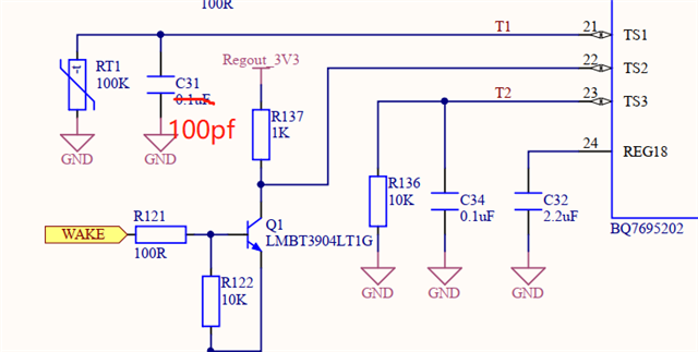
    您看看除了TS1相关的原理图外还需要哪一部分?目前电压电流采样值都正常,就是温度这里有问题,麻烦帮忙看看,谢谢了!~

  • 您好,Your schematic seems fine. Just to confirm whether this is an issue with the ADC calculation or with the actual hardware, can you provide the raw ADC measurements from while the device is exhibiting this behavior?

    You can find the registers to get these values from Section 4.6: Subcommands 0x0075–0x0077 DASTATUS5–7(), Additional Measurements of the TRM.

  • TS1温度值为128时,读出来的原始值为1522282或1523628或1509391或1510016....,麻烦帮忙分析一下,谢谢!

  • 获取TS1 ADC原始数据的代码如下:

    U08 BQ769x2_ReadTS1AdcRaw(S32 *value)
    {
        return BQ769x2_SubCmdResponseInt4(BQ769X2_SUBCMD_DASTATUS6, 24, value);// TS1 ADC data
    }

    U08 BQ769x2_SubCmdResponseInt4(U16 command, U08 offset, S32 *value)
    {
    U08 TX_Reg[2] = {0x00, 0x00};
    U08 buf[4];
    U08 u08Result = 0;

    //TX_Reg in little endian format
    TX_Reg[0] = command & 0xff;
    TX_Reg[1] = (command >> 8) & 0xff;

    u08Result |= I2C_WriteReg(BQ769X2_CMD_SUBCMD_LOWER, TX_Reg, 2);
    SystemTickDelay(2);
    u08Result |= I2C_ReadReg(BQ769X2_SUBCMD_DATA_START + offset, buf, 4);
    if(u08Result)
    {
    *value = (S32)(buf[0] | buf[1] << 8 | buf[2] << 16 | buf[3] << 24); // little-endian byte order
    }

    return u08Result;
    }

  • 您好,请参考下面内容

    It looks like the ADC is reading ~0.545V, which, assuming an ideal 18k pull-up resistor, translates to ~7.8kohms on the thermistor. Looking at your thermistor curve that's 30~31ºC, so we can be quite certain that this is not a hardware issue.

    I recommend taking a look at the example code provided on the BQ76952 product page and seeing if using those functions has any difference on the reading.

  • 您好!

    设置引脚、读取温度和设置校准参数的代码我已经贴在上面,能帮忙检查下问题吗?

    程序流程是在76952进入配置模式后调用BQ769x2_SetEnableTS1和BQ76952_Set18kTempModeCalib函数,然后在FULLSCAN标志置位后再调用BQ769x2_ReadThermistorTemp函数读取温度。

  • 您好,非常抱歉,代码需要您自己确认。您可以参考BQ76952 网页提供的sample code