

Part Number: UCD3138ALLCEVM150
When I use a DPWM2 module and a comparator D to trigger a period-by-period current fault:
The setting of DPWM2 is:
In the open loop state, set the mode to normal mode, period value, and event 1, 2, 3, and 4 values to 10000, 500, 4500, 5500, and 9500
Set the blanking time A to 100(400ns) from start to end
The setting of comparator D is:
Set the comparison threshold to 100(1.95V) and connect the comparator to the DPWM2
The setting of CBC is:
CBC_ADV_CNT_EN Set this registerto 1 to enable CBC,Set the CBC PWM AB EN to 1,Set the CBC_MAX_COUNT to 4(Set the maximum number of consecutive CBC triggers to 4),Set CBC_FAULT_EN to 1 and lower DPWM if CBC_MAX_COUNT is exceeded.
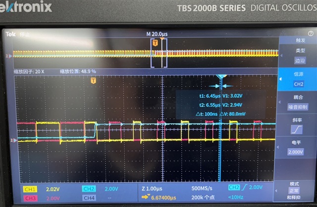
I get this waveform:
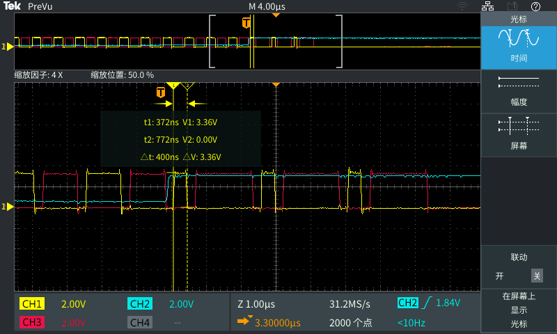
CH1 (yellow waveform) : indicates the output waveform of the DPWMA
CH2 (blue waveform) : Indicates the voltage sampled by comparator D
CH3 (red waveform) : indicates the output waveform of the DPWMB
Different trigger points have different effects on the waveform,I have a question about these waveforms:
If the falling edge of DPWMA is used as the trigger point, the DPWM wave will be lowered after 3 triggers at most, but I set 4 consecutive triggers in the Settings to lower the DPWM wave,so the trigger point for CBC is at which specific moment?
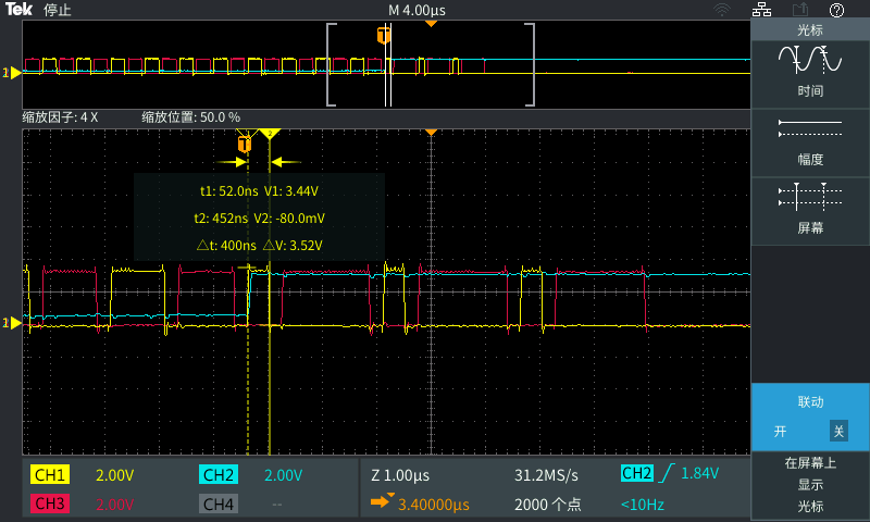
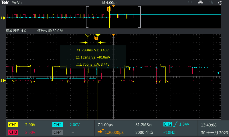
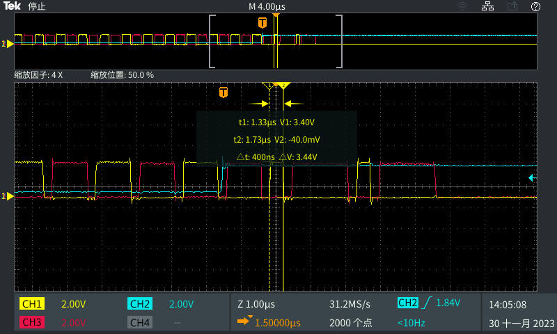
When I changed the mode to Multi mode, I set the start and end of blanking time B to 100, the start and end of blanking time A to 125, and set the duty cycle of DPWMA and DPWMB to match each other when triggered by CBC. When I set the trigger point to DPWMA and DPWMB under two different conditions, the following waveform was obtained:
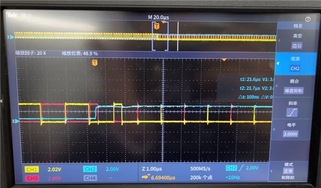
When the trigger point is in DPWMA, the subsequent output waveform is output according to the minimum duty cycle of DPWMA, that is, the value from the beginning to the end of the blanking register A; but when the trigger point is in DPWMB, the subsequent output waveform is not controlled by the start to the end of the blanking register B.