If you have a related question, please click the "Ask a related question" button in the top right corner. The newly created question will be automatically linked to this question.
您好,The BQ79616-Q1 device is able to detect open wire detection on the VC and CB pins. This is achieved through having a current sink connected to each VC and CB pin (except VC0 & CB0- this is connected with a current source).
If there is an open wire connection present and when the current sink is enabled, the external differential capacitor will be expended and the cell voltage measurement drops to an irregular level over time. This similarly applies to the VC0 & CB0 pins (with some minor changes).
When the diagnostic comparison is enabled, the device will compare cell voltage measurements between the Main ADC against either a host-programmed threshold or AUX CELL measurement (from the AUX ADC).
We have a more in-depth explanation of this process in the BQ79616-Q1 datasheethereand this can be found starting on page 95. I hope this helped!
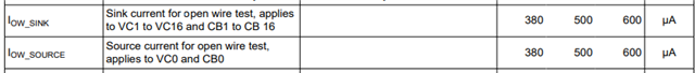
您好,You are correct that open-wire will be detected using a slightly different method on the bottom cell. Since the VC0 line is disconnected in this test, a source current instead of a sink current is used:
This is because the voltage at VC0 ~= GND. Without a significant voltage difference, enabling a current sink to GND to test open wire won't really affect the measured cell1 voltage because the capacitor won't be draining since both positive and negative terminals are at approximately the same voltage level.
Consequently, to detect open wire for VC0 and CB0, the BQ79616 uses a source current to raise the VC0 pin voltage. This means that the voltage difference between VC1 and VC0 should be smaller, leading to a reduced cell1 measured voltage. Please see Section 8.3.6.4.6.4 in the BQ79616 datasheet for more information: BQ79616 16-Series Battery Monitor, Balancer, and Integrated Hardware Protector datasheet (ti.com).
You mentioned a cell voltage increase. Is this the actual voltage measured across the cell by a multimeter, or is the BQ79616 reporting a higher cell1 voltage? Can you also show me where the customer is disconnecting the VC0 wire in an image?