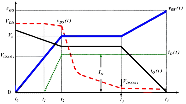
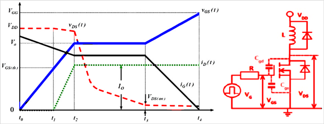
In some high-frequency switching circuits, the Miller effect of MOS tubes has the unpleasant disadvantages of extending the switching frequency, increasing power consumption, and reducing system stability. As shown in the figure below, there is a small flat step between t2 and t3, and the blue straight line part is the "Miller platform".
MOS tube conduction (Miller effect):
When MOSFET is turned on, Vds starts to drop and Id starts to rise, at which time MOSFET enters the saturation region; but due to the Miller effect, Vgs will not rise for a period of time, at which time Id has reached the maximum, and Vds continues to drop until the Miller capacitor is fully charged, and Vgs rises to the value of the driving voltage. At this time, MOSFET enters the resistance region, at which time Vds drops completely and the turn-on ends.
Miller effect: Since the Miller capacitor prevents the rise of Vgs, it also prevents the fall of Vds, which will prolong the loss time and increase the loss.
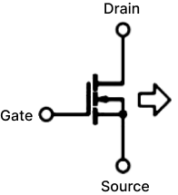
The left figure below is the circuit symbol diagram of the MOS tube, and the right figure is the equivalent model of the MOS tube.
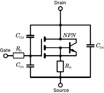
Miller capacitance shown in the figure
Cgs: GS parasitic capacitance
Cgd: GD parasitic capacitance
Input capacitance Ciss = Cgs + Cgd
Output capacitance Coss = Cgd + Cds
Reverse transfer capacitance Crss = Cgd
Miller effect refers to the effect of the equivalent input capacitance value being amplified by the distributed capacitance Cgs between the input and output under the effect of inverting amplification. The Miller effect will form a Miller platform.
Disadvantages of Miller effect:
From the first figure, we can see that under inductive load, the switching process of the MOS tube is significantly prolonged due to the Miller effect. The longer the D and S poles of the MOS tube overlap, the greater the conduction loss will be.
Miller capacitance is bound to exist due to the manufacturing process of MOS tubes, so it cannot be completely eliminated.
However, we can reduce the impact of the Miller effect by reducing the gate resistance Rg.
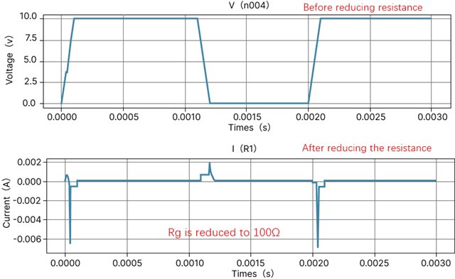
It can be seen that the smaller R1 is, the faster gs is charged and the faster the MOS tube is turned on.
However, is the Miller effect really useless?
We know that everything has two sides, and the existence of the Miller effect is bound to be so.
We can use the Miller effect to achieve the purpose of slow start of the circuit.
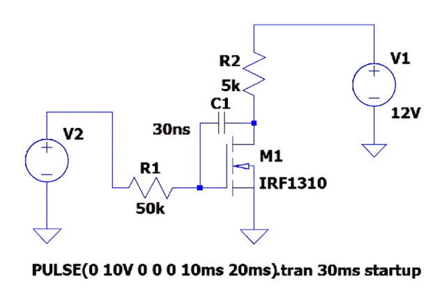
By increasing the gate resistance of the MOS tube and connecting a large capacitor in parallel between the G-D poles of the MOS tube, the Miller step can be artificially lengthened.
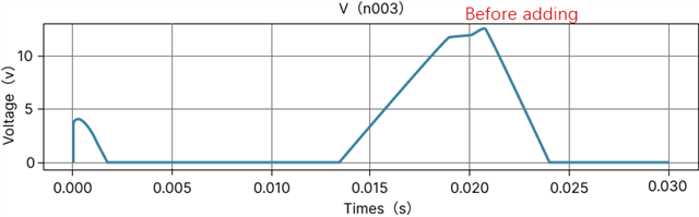
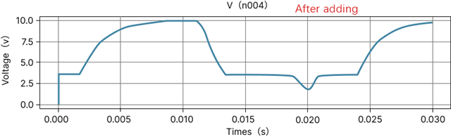
The circuit in the figure below increases the parallel capacitance between the gate resistance and the G-D pole, increases the Miller step, and turns the output waveform into a triangular pulse.