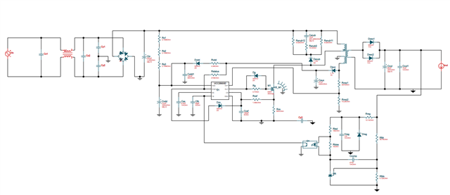
元器件参数参考UCC28600的计算表格,元器件电气连接参考WEBENCH® POWER DESIGNER 。
参考原理图(部分元器件参数非原理图内参数):
计算表格slvc104j:
| Summary of Ideal Converter Components | |||
| Xfmr | LPRI(terminal) | 5.8E-5 | H |
| LPRI(leakage) | 1.5E-6 | H | |
| NPRI/NSEC | 3.650 | turns ratio | |
| IPRI(rms) | 3.474 | ARMS | |
| IPRI(peak) | 8.954 | APEAK | |
| ISEC(rms) @ low line | 12.958 | ARMS, for non-PFC design | |
| ISEC(rms) @ high line | 10.558 | ARMS, for PFC design | |
| MOSFET | VDS rating | 600 | V |
| VDS stress | 510 | V | |
| ID(rms) | 3.474 | A | |
| Output capacitor | COUT | 8.6E-4 | F |
| ESR, max | 1.5E-3 | W | |
| rms current rating @ low line | 10.958 | ARMS | |
| rms current rating @ high line | 7.976 | ARMS | |
| Output Diode | VF | 0.7 | V |
| IAVERAGE | 6.917 | A | |
| IRMS | 12.958 | A | |
| IPEAK | 32.681 | A | |
| PDISSIPATE | 4.842 | W | |
| VBLOCK | 126.675 | V | |
| R current sense | RCS | 8.0E-2 | W |
| maximum power | 1.455 | W | |
| R power limit | RPL | 1.6E+3 | W |
| R2CD snubber | CSNUB | 5.0E-9 | F |
| RSNUB1 | 2.6E+3 | W | |
| PRsnub1 | 5.198 | W | |
| RSNUB2 | 16.960 | W | |
| OVP | ROVP1 | 1.6E+5 | W |
| ROVP2 | 4.1E+4 | W | |
| Soft start | CSS | 1.8E-8 | F |
| tSS | 6.1E-3 | s | |
| Minimum VDD Capacitor | CVDD | 1.5E-5 | F |
| Series resistor | RVDD | 6.21 | W |
| Start up resistor | RSU | 3.8E+6 | W |
| Transformer Data | |||||
| Actual Leakage to magnetizing inductance % (from magnetic manufacturer's drawing spec) | 2 | % | Leakage to magnetizing inductance ratio | 0.02 | |
| Actual LM (from magnetic manufacturer's drawing spec). The recommended primary inductance is shown in cell E42, carried over from the QR Design page. | 5.7E-5 | H | Recommended LM carried over from QR Design page and shown for the User's convenience in cell E42 | 5.8E-5 | H |
| LLEAKAGE | 1.1E-6 | H | |||
| Total L, primary | 5.8E-5 | H | |||
| Input the actual Primary to Secondary Turns Ratio, from the magnetic manufacturer's drawing spec, into cell B47. This value should very closely match the recommended turns ratio calculated on the QR Design Tool sheet and shown for the User's convenience in cell E47 of this sheet. | |||||
| NPRI/NSEC (from magnetic manufacturer's drawing spec) | 3.666 | turns ratio | 3.650 | Recommended NPRI/NSEC turns ratio | |
| VXFMR, reflect | 90.550 | V | Recommended VXFMR, reflect | 90.2 | V |
| Input the actual Primary to Bias Turns Ratio, from the magnetic manufacturer's drawing spec, into cell B50. This value should very closely match the recommended turns ratio calculated on the QR Design Tool sheet and shown, for the User's convenience, in cell E50 of this sheet. | |||||
| NPRI/NBIAS | 5.500 | 5.840 | Recommended NPRI/NBIAS turns ratio | ||
| ACTUAL Output Voltage | 24 | V | |||
| ACTUAL Bias Voltage | 15.99709091 | V | |||
| Sense Resistors & Power Limit | Recommended values, carried over from the QR Design Tool page and adjusted for the actual turns ratio are shown in cells D54 through D57. The User must insert the closest standard value for each component in cells B54 through B57, iterating until the recommended values no longer self-adjust (usually 2-3 iterations are all that are needed) | ||||
| RCS, current sense | 0.080 | W | 0.081 | W | |
| RPL, power limit | 1.50E+03 | W | 1.43E+03 | W | |
| ROVP1 | 1.5E+5 | W | 1.7E+5 | W | |
| ROVP2 | 3.6E+4 | W | 4.1E+4 |
W |
|
变压器设计:(Lp=56uH)
| 匝数比 | 原边 | 输出24V | 输出5V | 副边15V | |
| Npri/Nsec1 | 3.688194859 | Npri 1-3 | Nsec1 9-12 | Nsec2 8-7 | Nbais 5-6 |
| Npri/Nbais | 5.901111775 | 22 | 5.964977676 | 1.242703683 | 3.728111048 |
| 最终计算匝数 | 22 | 6 | 2 | 4 |
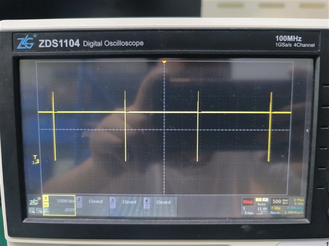
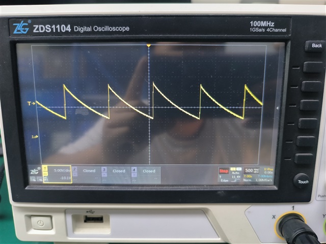
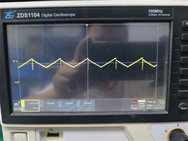
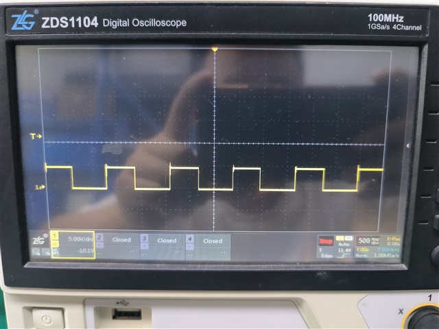
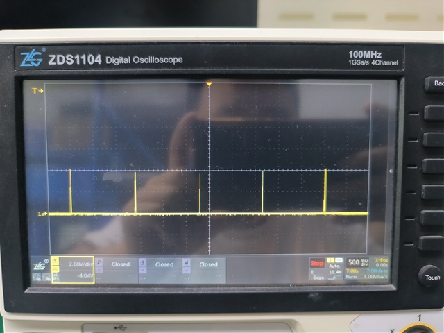
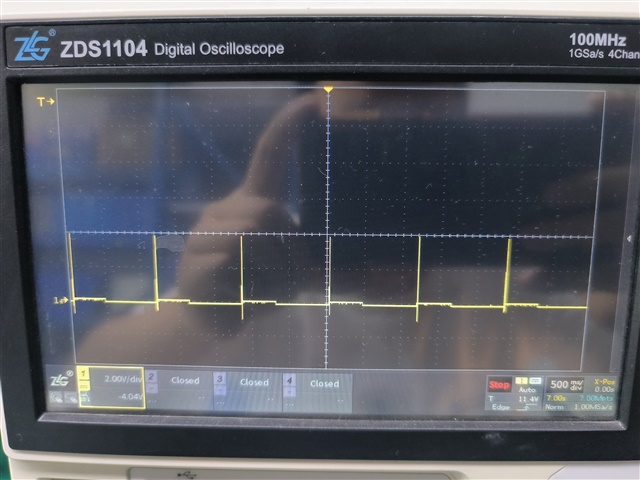
部分波形图:
Vout24V
Pin-Vdd
pinFB
Pin-SS
Pin-OVP
Mos-DS