This thread has been locked.

If you have a related question, please click the "Ask a related question" button in the top right corner. The newly created question will be automatically linked to this question.

BOOSTXL-TPS65033: connected to USB2ANY Controller, but failed to connect to device TPS65033x on I2C @0x60

Part Number: BOOSTXL-TPS65033
Other Parts Discussed in Thread: USB2ANY

Hello There,

I want to used the tool program PMIC, but failed with error info: connected to USB2ANY Controller, but failed to connect to device TPS65033x on I2C @0x60

my question is :

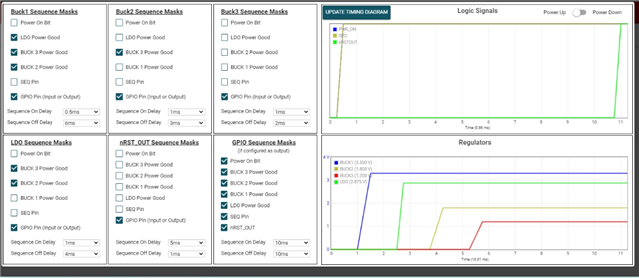
  • I am using IC TPS65033104, my colleague told me that this chip can't be program as we need to use PTPS65033 version, is that true? I have a hint that the chip I am using can measure the output voltage even I can't find it through I2C bus, buck1 is 3V3, buck2 is 1V8, Buck3 is 1V2, LDO is 2V8.
  • if the question above is not true, how can I solve the problem? for example, the jumper checking?
  • Hello,

    I have tried for several pcs, none of them can be accessed.

    and I also uninstall the GUI fromV1.0.2 and install V1.0.0, also doesn't work.

    do you have any other hints about the problem?

    also help to confirm whether only component with first letter is P, for example PTPS65033 instead of TPS65033 that can be configurable.

  • Hi inks,

      The OPN "TPS65033104RGERQ1" is a mass production function safety variant which has no "P" as the first letter; all PNs start with a "P" are sample phase devices. All function safety variants in mass production have been disabled for re-programming its NVM.

      Yes; you can measure the output voltage even without I2C operation; buck1=3.3V, buck2=1.8V, Buck3=1.2V, LDO=2.875V with power on sequence showing by GUI screenshot below:

      All power rails output levels can be changed by I2C writing to related registers but not to its NVM which means all levels come back to default values set by NVM after power recycle. 

      Please follow its User guide linked here to use the setup properly. 

    Thanks!

  • Hello,

    Thank you for your info.

    Right now I still have 3 questions:

    1) can I undertsand that when I use the component what I have now, the tool of BOOSTXL-TPS6503x also can't have access to the memory by the GUI, which means the problem I have now is a normal behavior?

    2) If yes, can you provide me a type that can be configured? then I can buy it and do the configuration using the GUI by my self.

    3) Can you provide me the list that contains all the pre-configured fixed output voltage in the mass production in this series? so that I can ignore this tool problem and can buy one configurated component.  my desired output voltage is BUCK1 = 3V8(this can be higer as this is used for primary buck), buck 2 = 1V1, BUCK3 = 1V8, LDO = 3V3.

    Thank you in advance!

  • My answers are listed below:

    1) You can have access to the memory (open to customers) by the GUI if you follow the user guide of the tool of BOOSTXL-TPS6503x.

    2) Please follow the user guide of the tool of BOOSTXL-TPS6503x. (

    www.ti.com/.../slvubo3a.pdf


    3) Attached below is the JSON file with all detail configurations for the OPN "TPS65033104RGERQ1".

    {
        "my_model": {
            "$refresh_interval": 1,
            "PID": 196,
            "RID": 73,
            "CONTROL_LOCK": 0,
            "BUCK_LDO_CTRL": 31,
            "GPIO_CTRL": 31,
            "CONFIG_LOCK": 0,
            "LDO_GPIO_CFG": 4,
            "BUCK1_VOUT": 16,
            "BUCK1_UVLO": 2,
            "BUCK2_VOUT": 29,
            "BUCK3_VOUT": 10,
            "LDO_VOUT": 17,
            "DISCHARGE_SETTING": 85,
            "SEQ_TRIG_BUCK1": 30,
            "SEQ_TRIG_BUCK2": 10,
            "SEQ_TRIG_BUCK3": 2,
            "SEQ_TRIG_LDO": 26,
            "SEQ_TRIG_nRSTOUT": 2,
            "SEQ_TRIG_GPIO": 127,
            "BUCK1_SEQ_DLY": 113,
            "BUCK2_SEQ_DLY": 66,
            "BUCK3_SEQ_DLY": 50,
            "LDO_SEQ_DLY": 82,
            "nRSTOUT_SEQ_DLY": 38,
            "GPIO_SEQ_DLY": 187,
            "INT_ACK": 0,
            "INT_ACK_BUCK1": 0,
            "INT_ACK_BUCK2": 0,
            "INT_ACK_BUCK3": 0,
            "INT_ACK_LDO": 0,
            "INT_MASK_BUCKx_LDO": 255,
            "FAULT_STATUS_BUCK1": 0,
            "FAULT_STATUS_BUCK2": 0,
            "FAULT_STATUS_BUCK3": 0,
            "FAULT_STATUS_LDO": 0,
            "VMON_BUCK1_CFG": 15,
            "VMON_BUCK2_CFG": 10,
            "VMON_BUCK3_CFG": 15,
            "VMON_LDO_CFG": 0,
            "ERR_BUCKx_LDO_CFG": 0,
            "RESTART_CMD": 0,
            "CFG_REG_CRC": 0,
            "DEV_STAT": 12,
            "DEV_ERR_ACK_1": 0,
            "DEV_ERR_ACK_2": 0,
            "DEV_FAULT_STATUS_1": 0,
            "DEV_FAULT_STATUS_2": 0,
            "INT_MASK_SAFETY": 3,
            "PIN_MON_ERR_CFG": 0,
            "ABIST_GROUP_DONE": 0,
            "ABIST_BUCK1_2_ACK": 0,
            "ABIST_LDO_BUCK3_ACK": 0,
            "ABIST_SYSTEM_ACK": 0,
            "ABIST_RUN_CMD": 0,
            "POWER_GOOD_STATUS": 0,
            "EEPROM_PROG_CMD": 0
        }
    }