LM76002: Can I use SS/TRK pin as external reference input.

Part Number: LM76002
Other Parts Discussed in Thread: TPS54360B, TPS54260

I'm building a 4-phase interleaved Buck converter with LM76002. The MCU provides interleaved clocks for LM76002s. The main purpose is to get extremely low ripple voltage.

In my test board, I've noticed that there seems to be some problem on current sharing. 

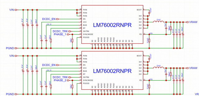
There's four chips in total, which only two of them are shown in the picture.

Vin = 20V, fsw = 1MHz, Vout = 7.6V, Iout = 2A. FB pins of the four chips are tied together.

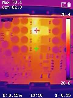
I found one of the four chips obviously hotter that others. The inductors show the same thing better. I tested the waveforms at SW node of each LM76002. The duty cycle of the hotter chip is slightly higher. The hotter chip of different boards are not the same position. I think it's mainly because the internal reference voltage has difference.

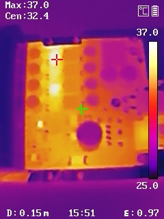
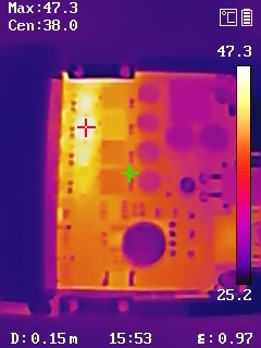
(These two pictures were take not long after start up, so the temperatures are lower than that of above one.)

I tried to apply about 0.9V on the SS/TRK pin, and it seems better. At least the four inductors shows similar temperature. The first picture shows similar inductor temperature, which has 0.9V on SS/TRK. The second picture shows one hotter chip and one hotter inductor, has 1.25V on SS/TRK.

My question is that can I use it like this in long term operations? Current sharing is a big issue for me because I'd like to use it with heavier load, maybe up to 8A. (I've designed heat sink and it's not installed at present.)

And another small question. Will it damage the LM76002 when BIAS is 5 Volts but PVIN is 0 Volts for long time? Or will current flow reversely from BIAS to PVIN?

I'm using other step down converters for circuits like MCU, ADC and DAC, so there's easily accessible 5V for external BIAS. And there's a relay in PVIN as circuit breaker providing additional protections. I'd like to avoid protection designs causing new damage.

  • These converters are internally compensated thus not recommended connecting them in parallel. Mismatch between devices would lead to uneven current sharing.

    If you are in early design phase you could consider TPS54260/TPS54360B here.

    My question is that can I use it like this in long term operations? Current sharing is a big issue for me because I'd like to use it with heavier load, maybe up to 8A. (I've designed heat sink and it's not installed at present.)

     - Yes , you can do that. However, keep it below the internal reference voltage for proper operation.

    And another small question. Will it damage the LM76002 when BIAS is 5 Volts but PVIN is 0 Volts for long time? Or will current flow reversely from BIAS to PVIN?

    - I am checking this internally. I'll get back to once I get necessary information.

  • If you are in early design phase you could consider TPS54260/TPS54360B here.

    I've already built sample boards. And the expected load will be a slowly adjustable constant current source, which has little requirements on transient response. So it seems that only current sharing is the problem. I'll do further test to check if there's any problem caused by the internal compensation mismatch.

     - Yes , you can do that. However, keep it below the internal reference voltage for proper operation.

    Well, that great. I will keep it below 0.95V.

    - I am checking this internally. I'll get back to once I get necessary information.

    Have you got any new discoveries on this? It's the only remaining question I have before building the next version. Thanks very much on your reply.

  • And another small question. Will it damage the LM76002 when BIAS is 5 Volts but PVIN is 0 Volts for long time? Or will current flow reversely from BIAS to PVIN?

    There is no major risk in do this, however, there is possibility of current to leak from parasitic path. I would recommend avoiding it.