Hello ,
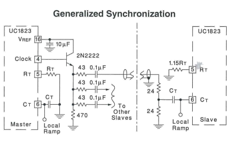
I would like to ask how to do SYNC between UC3825 and UC3823 control ICs.
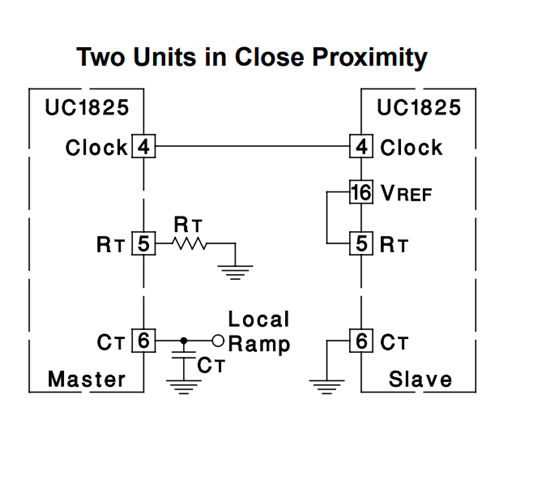
I actually used two UC3825 jumpers to connect them first. The data table below illustrates how the two units are close together.
After connecting it, I found that SLAVE will not output PWM signal.
If Vref is connected to RT at 5.1V, make sure the connection is correct.
My current circuit is in voltage mode, and P6 and P7 are connected together. But when using SYNC, is CT connected to ground correctly?
Please tell me how I should modify it or can you provide me with my circuit diagram for reference.
Thank you so much.

You should use this below approach if the one you used not working. It is likely the two chips are not close enough with too much noise, or two chips frequencies not able to decide to sync.
The below is able to adapt all these above.
Hi Vivian ,
Thank you for your reply. I will try these two methods and will update soon if there is any new information.
Thank you~
jun
Hi Vivian,
I connected the first synchronization method and found out that Slave UC3825 does not have a Ramp waveform when I hooked up the oscilloscope.
My question is when I want to connect a synchronization circuit, should the Master Local Ramp be connected to the Slave P7 (Ramp)?
At this time, does the Slave still need to connect P7 and P6 together to form Voltage Mode?
Thank you~
Please clarify what you mean P7 and P6. It sounds you mean P6 is master IC and P7 is slave IC. I assume what you mentioned "the first sync" is to connect their clock together.
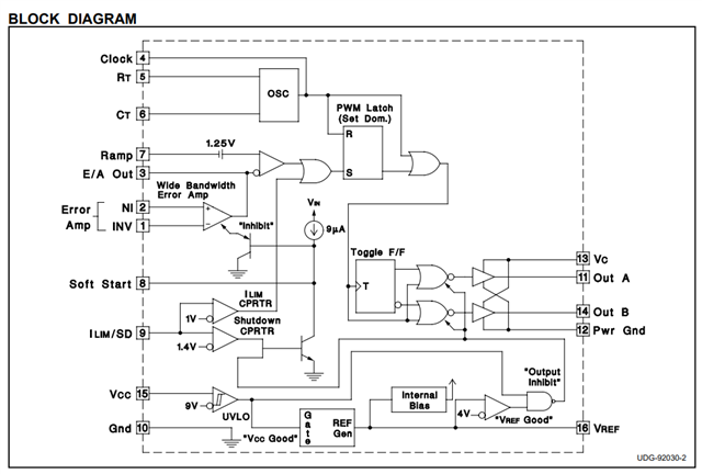
Based on the block diagram in the datasheet, the RAMP is still required for both P6 and P7. Without RAMP R-S flip-flop cannot be "Set", then you cannot see the OutA and OutB on off so no pulses can be seen from the two outputs.