

Part Number: BQ77216
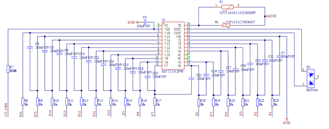
采用如图电路设计,使用BQ7721612芯片。发现:
1、部分芯片焊接到PCB后接上电池工作正常,部分芯片不断输出报警。
2、有问题芯片,仅从C17_PWR供电50V的情况下,COUT输出高电平7V,DOUT输出低电平。工作正常的芯片,两个脚都输出低电平。
这个现象是电路中有哪个位置设计有问题导致的?
Part Number: BQ77216
采用如图电路设计,使用BQ7721612芯片。发现:
1、部分芯片焊接到PCB后接上电池工作正常,部分芯片不断输出报警。
2、有问题芯片,仅从C17_PWR供电50V的情况下,COUT输出高电平7V,DOUT输出低电平。工作正常的芯片,两个脚都输出低电平。
这个现象是电路中有哪个位置设计有问题导致的?

