

Other Parts Discussed in Thread: DLP5531-Q1, LM5175
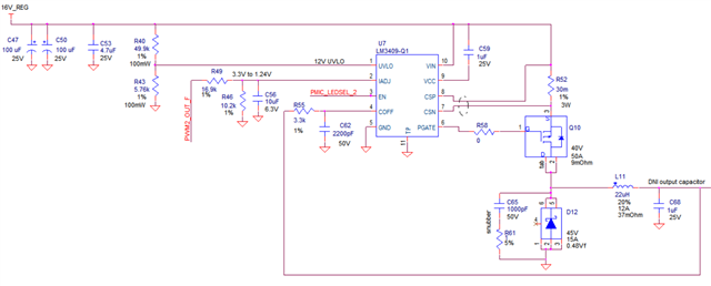
以TI的 DLP5531-Q1的公版驱动电路为基础
更换光源进行驱动,需修改驱动参数
第一种为7.4V LED开关峰值电流16A
第二种为7.0V LED开关峰值电流12A
请问原设计应该修改哪些器件参数
以TI的 DLP5531-Q1的公版驱动电路为基础
更换光源进行驱动,需修改驱动参数
第一种为7.4V LED开关峰值电流16A
第二种为7.0V LED开关峰值电流12A
请问原设计应该修改哪些器件参数

