

Part Number: AM625
Dear TI Support Team,
I am currently working with the AM6254A processor and using SDK version 09.02.01.09. For reference, the documentation I’m following is titled "AM62x Processors Silicon Revision 1.0 – Texas Instruments Families of Products."
I would like to configure CPTS_RFT_CLK sourced from CP_GEMAC_CPTS0_RFT_CLK, and I have performed the following steps:
-
I configured the general-purpose register 0x000F41F0 for the
CP_GEMAC_CPTS0_RFT_CLKpin A18 with the value0x08254006, enabling the input function and setting the pin mux toCP_GEMAC_CPTS0_RFT_CLK. -
Based on the requirements, I attempted to configure the
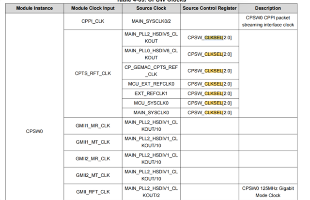
CPTS_CLKSELregister to selectCP_GEMAC_CPTS0_RFT_CLKas the input source. I also intend to feed in a clock signal ranging from 125MHz to 650MHz (I have an external PLL capable of outputting a sine wave within this frequency range).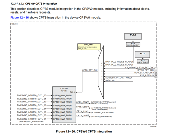
I now have the following questions and would appreciate your guidance:
-
Are the above configuration steps feasible and valid for setting up
CP_GEMAC_CPTS0_RFT_CLKas the source forCPTS_RFT_CLK? -
If I input a 125MHz signal to
CP_GEMAC_CPTS0_RFT_CLK, what are the required electrical levels and waveform characteristics (e.g., voltage standard, duty cycle, waveform shape)? -
I was unable to locate the following registers or fields in the documentation:
-
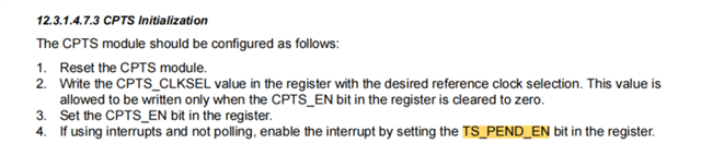
CPTS_CLKSEL -
CPTS_EN -
TS_PEND_EN -
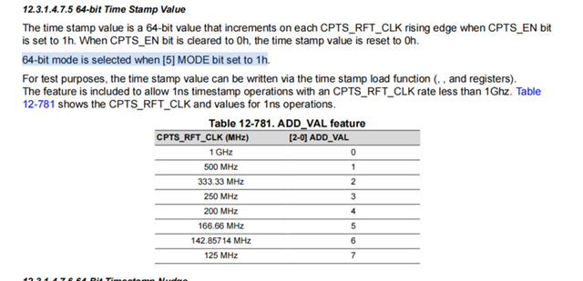
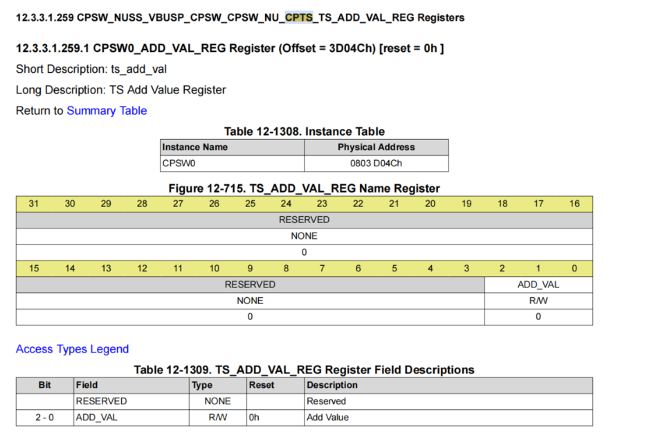
ADD_VAL[2-0] -
The
MODE[5]bit which is mentioned in the phrase: “64-bit mode is selected when [5] MODE bit set to 1h”
I did find references that may correspond to these:
-
CPTS_CLKSELmight beCPSW_CKJSEL -
ADD_VAL[2-0]might correspond toCPSW_NUSS_VBUSP_CPSW_NU_CPTS_TS_ADD_VAL_REG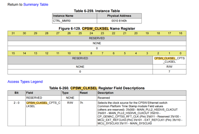
However, I could not find clear documentation for the others. Could you please confirm their correct register names and locations?
-
-
I came across the following forum post, which discusses using device tree configuration for AM64x:
In that post,
AM64X_DEV_CPSW0has mapped clock IDs. How can I identify or trace similar clock mapping IDs for the AM6254A in the device tree or TI SDK? -
Are there any existing reference implementations or sample configurations available for using
CP_GEMAC_CPTS0_RFT_CLKas the CPTS reference clock input?
Thank you in advance for your support and guidance.
Best regards,
TiAmo
